
Page 237 - Organic Electronics in Sensors and Biotechnology
P. 237
214 Cha pte r S i x
10 –2
Current (A) 10 –4
–6
10
Dark
0.0063
0.0126
0.123
10 –8 0.63
1.26
–1 –0.8 –0.6 –0.4 –0.2 0 0.2 0.4 0.6 0.8 1
Applied bias (V)
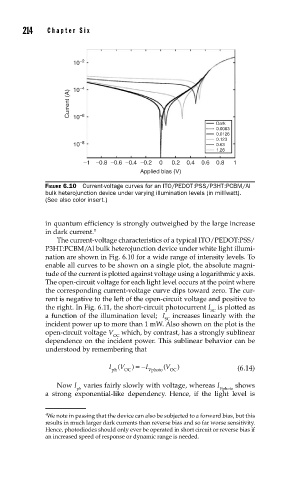
FIGURE 6.10 Current-voltage curves for an ITO/PEDOT:PSS/P3HT:PCBM/Al
bulk heterojunction device under varying illumination levels (in milliwatt).
(See also color insert.)
in quantum efficiency is strongly outweighed by the large increase
in dark current. †
The current-voltage characteristics of a typical ITO/PEDOT:PSS/
P3HT:PCBM/Al bulk heterojunction device under white light illumi-
nation are shown in Fig. 6.10 for a wide range of intensity levels. To
enable all curves to be shown on a single plot, the absolute magni-
tude of the current is plotted against voltage using a logarithmic y axis.
The open-circuit voltage for each light level occurs at the point where
the corresponding current-voltage curve dips toward zero. The cur-
rent is negative to the left of the open-circuit voltage and positive to
the right. In Fig. 6.11, the short-circuit photocurrent I is plotted as
SC
a function of the illumination level; I increases linearly with the
SC
incident power up to more than 1 mW. Also shown on the plot is the
open-circuit voltage V which, by contrast, has a strongly sublinear
OC
dependence on the incident power. This sublinear behavior can be
understood by remembering that
I ( V ) =− I ( V ) (6.14)
ph OC V photo OC
Now I varies fairly slowly with voltage, whereas I shows
ph Vphoto
a strong exponential-like dependency. Hence, if the light level is
† We note in passing that the device can also be subjected to a forward bias, but this
results in much larger dark currents than reverse bias and so far worse sensitivity.
Hence, photodiodes should only ever be operated in short circuit or reverse bias if
an increased speed of response or dynamic range is needed.