Page 242 - Organic Electronics in Sensors and Biotechnology
P. 242

An Intr oduction to Or ganic Photodetectors     219


                            = RC ln 9       Δt = RC ln 9
                         Δt r                 f

                         1                                   C
                                90%
                      Normalized photovoltage  0.6           R L
                        0.8


                        0.4


                        0.2    Excitation pulse
                                10%
                         0
                           0      5     10    15     20    25     30
                                           Time (AU)

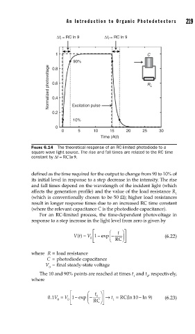
               FIGURE 6.14  The theoretical response of an RC-limited photodiode to a
               square wave light source. The rise and fall times are related to the RC time
               constant by Δt = RCln 9.


               defined as the time required for the output to change from 90 to 10% of
               its initial level in response to a step decrease in the intensity. The rise
               and fall times depend on the wavelength of the incident light (which
               affects the generation profile) and the value of the load resistance R
                                                                        L
               (which is conventionally chosen to be 50 Ω); higher load resistances
               result in longer response times due to an increased RC time constant
               (where the relevant capacitance C is the photodiode capacitance).
                   For an RC-limited process, the time-dependent photovoltage in
               response to a step increase in the light level from zero is given by
                                        ⎡     ⎛   t ⎞⎤
                                Vt() =  V ⎢ 1  −  exp −  ⎟⎥         (6.22)
                                              ⎜
                                       0           ⎠
                                        ⎣     ⎝ RC  ⎦
               where  R = load resistance
                      C = photodiode capacitance
                     V  =  final steady-state voltage
                      0
                   The 10 and 90% points are reached at times t  and t , respectively,
                                                        1    2
               where
                               ⎡      ⎛  t ⎞⎤
                                                          −
                                 −
                      01V =  V 0 ⎢ 1 exp −  1  ⎥ →  t = RC (ln 10 − ln )  (6.23)
                                                              9
                       .
                          0           ⎜    ⎟    1
                               ⎣ ⎢    ⎝ RC ⎠ ⎥ ⎦
   237   238   239   240   241   242   243   244   245   246   247