
Page 239 - Organic Electronics in Sensors and Biotechnology
P. 239
216 Cha pte r S i x
R s
I s D C R sh R L
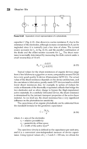
FIGURE 6.12 Equivalent circuit representation of a photodiode.
capacitor C (Fig. 6.12). Also shown is a series resistance R due to the
s
resistance of the electrodes, although in many circumstances R can be
s
neglected since it is normally just a few tens of ohms. The current
source accounts for I in Eq. (6.11), and the parallel combination of
ph
the diode and the shunt resistor accounts for I . The shunt resis-
dark
tance is normally determined by measuring the dark current under a
small reverse bias of 10 mV.
.
−001 V
R = (6.15)
sh
I −001( . V)
d
Typical values for the shunt resistances of organic devices range
from a few kilohms to a gigaohm or more, compared to around 50 GΩ
for a very good quality Si device (Hamamatsu S4797-01). The actual
value of the shunt resistance depends on the device architecture, and
the care taken in fabrication; poorly made OPV devices tend to exhibit
lower shunt resistances due, for example, to spikes of indium tin
oxide or filaments of the thermally evaporated cathode that bridge the
two electrodes and so allow charge to bypass the (high-impedance)
active materials. In a carefully fabricated device, the shunt resistance
is determined by the intrinsic transport properties of the active layer
material. As we shall see, the shunt resistance has a very significant
influence on the photodetector sensitivity.
The capacitance of an organic photodiode can be estimated from
the standard formula for the geometric capacitance
Aεε
C = r 0 (6.16)
d
where A = area of the electrodes
ε = relative permittivity
r
ε = permittivity of free space
0
d = width of the active layer 48
The capacitance density is defined as the capacitance per unit area,
and it is a convenient area-independent measure of device capaci-
tance. Using typical values of ε = 3 and d = 100 nm, we obtain for
r