
Page 142 - Phase Space Optics Fundamentals and Applications
P. 142
The Radon-Wigner Transform 123
Exit pupil
Focal plane
y
Observation
x point
φ
ar N
a
Σ P f
z
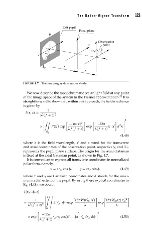
FIGURE 4.7 The imaging system under study.
We now describe the monochromatic scalar light field at any point
of the image space of the system in the Fresnel approximation. 21 It is
straightforwardtoshowthat,withinthisapproach,thefieldirradiance
is given by
1
I (x,z) = 2 2
( f + z)
2
2
−i z|x | −i2
× P(x ) exp exp x · x d x
2
f ( f + z) ( f + z)
P
(4.48)
where is the field wavelength, x and z stand for the transverse
and axial coordinates of the observation point, respectively, and P
represents the pupil plane surface. The origin for the axial distances
is fixed at the axial Gaussian point, as shown in Fig. 4.7.
It is convenient to express all transverse coordinates in normalized
polar form, namely,
x = ar N cos , y = ar N sin (4.49)
where x and y are Cartesian coordinates and a stands for the maxi-
mum radial extent of the pupil. By using these explicit coordinates in
Eq. (4.48), we obtain
¯ I(r N , ,z)
2 1
1 i2 W(r , ) i2 W 20 (z) r 2
N
N
= ¯ p(r , ) exp exp
N
2
( f + z) 2
0 0
2
−i2
× exp r r N cos( − ) r dr d (4.50)
N
N
N
( f + z)