
Page 109 - Phase-Locked Loops Design, Simulation, and Applications
P. 109
MIXED-SIGNAL PLL ANALYSIS Ronald E. Best 72
ω . Consequently, the average output signal of the phase detector is a sine wave having
0
the frequency Δω, which is an AC signal. We now assume that the frequency offset Δω is so
large that a lock-in process will not take place. Because the frequency offset Δω is generally
much larger than the corner frequencies 1/τ and 1/τ of the loop filter, the loop filter will
2
1
attenuate the signal. The loop filter output signal will also be a sine wave with radian
frequency Δω, and the u signal will again modulate the frequency of the VCO output, as has
f
been shown in Fig. 3.10.
If u were a perfect sine wave, its average value would be 0, hence the average output
f
frequency of the VCO would stay stuck at its center frequency ω . Under these conditions, the
0
PLL would never pull in!
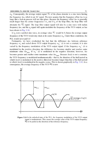
Fortunately, we have overlooked the fact that the difference Δω between reference
frequency ω and scaled down VCO output frequency ω ′(t) is not a constant; it is also
2
1
varied by the frequency modulation of the VCO output signal. If the frequency ω ′(t) is
2
modulated in the positive direction, the difference Δω becomes smaller and reaches some
minimum value Δω min . If ω ′(t) is modulated in the negative direction, however, Δω
2
becomes greater and reaches some maximum value Δω . Because Δω(t) is not a constant,
max
the VCO frequency is modulated nonharmonically—that is, the duration of the half-period in
which Δω(t) is modulated in the positive direction becomes longer than that of the half-period
in which Δω(t) is modulated in the negative sense. This is shown graphically in Fig. 3.14. As a
consequence, the average frequency of the VCO is now
Figure 3.14 In the unlocked state of the PLL, the frequency modulation of the VCO output
signal is nonharmonic. This causes the average value of the VCO output frequency
to be pulled in the direction of the reference frequency.