
Page 111 - Phase-Locked Loops Design, Simulation, and Applications
P. 111
MIXED-SIGNAL PLL ANALYSIS Ronald E. Best 73
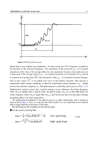
Figure 3.15 The pull-in process.
higher than it was without any modulation—in other words, the VCO frequency is pulled in
the direction of the reference frequency. The asymmetry of the waveform ω ′(t) is greatly
2
dependent on the value of the average offset Δω; the asymmetry becomes more marked as Δω
is decreased. If the average value of ω ′(t) is pulled somewhat in the direction of ω (which
2 1
is assumed to be greater than ), the asymmetry of the ω ′(t) waveform becomes stronger.
2
This in turn causes to be pulled even more in the positive direction. This process is
regenerative under certain conditions, so that the scaled-down output frequency ω ′ finally
2
reaches the reference frequency ω This phenomenon is called the pull-in process (Fig. 3.15).
1.
Mathematical analysis shows that a pull-in process occurs whenever the initial frequency
offset Δω is smaller than a critical value, the pull-in range Δω . If, on the other hand, the
0
P
initial frequency offset Δω is larger than Δω , a pull-in process does not take place because
0 P
the pulling effect is not then regenerative.
The mathematical treatment of the pull-in process is quite cumbersome and is treated in
more detail in App. A. Here, we only give the final results. It is very important to note that the
pull-in range depends on the type of loop filter.
The following are the formulas for the pull-in range:
■ For the passive lead-lag filter
(3.69)