
Page 113 - Phase-Locked Loops Design, Simulation, and Applications
P. 113
MIXED-SIGNAL PLL ANALYSIS Ronald E. Best 74
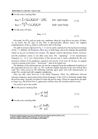
■ For the active lead-lag filter
(3.70)
■ For the active PI filter
(3.71)
Obviously, the PLL pulls in under any conditions when the loop filter is an active PI filter.
As we know, the DC gain of this filter is (theoretically) infinite; hence, the slightest
nonharmonicity of the u signal is sufficient to pull in the loop.
d
The pull-in process depicted in Fig. 3.15 can be easily explained by the mechanical analogy
of Fig. 3.7. Initially, the frequency offset Δω is fairly large, and in the analogy the pendulum
0
rotates at Δω /2π revolutions per second. The angular velocity decelerates slowly, however,
0
and the pendulum comes to rest after some time. The “pumping” of the instantaneous
frequency ω ′(t) is very characteristic of this process and is easily explained by the non-
2
harmonic rotation of the pendulum caused by the gravity of its mass M. In fact, its angular
velocity is greater at the lower “dead point” than at the higher one.
The duration of the pull-in process can also be computed from the mathematical analysis of
the acquisition process (see App. A). The result also slightly depends on the type of loop filter
used. The values given by the following formulas agree quite well with measurements on
actual PLL circuits and with computer simulations.
They are only valid, however, if the initial frequency offset Δω (difference between
0
reference frequency and [scaled down] initial frequency of the VCO) is distinctly smaller than
the pull-in range, typically less than 0.8 times the pull-in range. When Δω approaches the pull-
in range Δω , the pull-in time T approaches infinity; thus, the formula cannot be used.
P P
The analysis gives the results:
■ For the passive lead-lag filter
(3.72)
■ For the active lead-lag filter
(3.73)
Printed from Digital Engineering Library @ McGraw-Hill (www.Digitalengineeringlibrary.com).
Copyright ©2004 The McGraw-Hill Companies. All rights reserved.
Any use is subject to the Terms of Use as given at the website.