
Page 128 - Phase-Locked Loops Design, Simulation, and Applications
P. 128
MIXED-SIGNAL PLL ANALYSIS Ronald E. Best 82
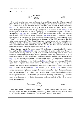
■ loop filter = active PI
(3.85)
It is worth considering a major difference of the pull-in processes for different types of
phase detectors. If the phase detector is an EXOR gate, the instantaneous frequency of the
VCO is modulated in both directions around its average value, as seen in the lower trace of
Fig. 3.16. This is to be expected, for the u signal is an AC signal. Provided a pull-in process
d
starts, the frequency of the VCO is slowly “pumped up,” as has been shown in Fig. 3.15 for
the multiplier phase detector. A similar “pumping” is observed when the phase detector is a
JK-flipflop (cf. Fig. 3.17). No “pumping” occurs, however, when the PFD is used. Since the
driving signal for the loop filter is unipolar here (cf. Fig. 3.19), charge is “pumped” into the
filter capacitor in one direction only, so that the frequency of the VCO is moved in the
“right” way at any time. The instantaneous frequency of the VCO approaches the final
value from one side only. When the pull-in process is completed, a lock-in process follows.
Only then does the output frequency perform a damped oscillation; it slightly overshoots the
final value and settles after the transient has died out. We will have a closer look at these
phenomena when we perform computer simulations in Chap. 10.
Phase detector type 4b. The current output PFD is almost always combined with a passive
lead-lag loop filter (cf. Fig. 2.17b), hence we can restrict discussion on this case. Because a
current-driven lead-lag filter has a pole at s = 0 and consequently behaves like a real
integrator, the pull-in range becomes infinite, like in the case of the voltage-driven PFD. To
compute the pull-in time T , we will use a model similar to that used for PFD type 4a (refer to
P
Fig. 3.19). For the voltage output PFD, the PFD output signal u is ramped up in a sawtooth-
d
like manner, as illustrated by the third trace in Fig. 3.18. For the current output PFD, this
signal must be replaced by a current output i . The average value of i also shows up as a
d
d
sawtooth waveform varying from 0 to I /2, where I is the amplitude of the current source in
P P
Fig. 2.16, which was defined in Eq. (2.26). Because I = K 2π [Eq. (2.27)] the time varying
P P
current source can be replaced by an equivalent current source I = K π. This current source
P
eq
now charges capacitor C of the loop filter. The pull-in time T is the time required to change
1 P
the voltage on capacitor C such that the (scaled-down) frequency of the VCO ω ′ becomes
2
1
equal to the frequency ω of the input signal. An analogous analysis of the pull-in process
1
yields the pull-in time
(3.86)
The truth about “infinite pull-in range”. Theory suggests that the pull-in range
becomes infinite whenever the loop filter is an active PI filter—that is, a filter having a pole at
s = 0 (or in other words, a filter having “infinite gain” at DC). As we already