
Page 278 - Phase-Locked Loops Design, Simulation, and Applications
P. 278
MIXED-SIGNAL PLL APPLICATIONS PART 2: FRACTIONAL-N FREQUENCY
SYNTHESIZERS Ronald E. Best 165
converter); the output signal u DAC is added to the output signal of the phase detector. Since
the two staircase signals cancel each other, the input signal to the loop filter is a DC level
when the fractional N loop has reached a stable operating point.
In the examples considered hitherto (cf. Figs. 7.1 and 7.2), the phase error showed up as a
repetitive pattern. In the first case, it repeated every second reference cycle, while in the
second example it repeated every tenth reference cycle. In the first case, a spur at half the
reference frequency is created, while in the second case the spur occurs at 1/10 of the
reference frequency. For other fractional parts F, the spurs can be at even smaller fractions of
the reference frequency. Digital spur reduction techniques offer means for “randomizing”
the phase error pattern. As a first consequence, the randomized error pattern is no longer
periodic. Moreover, the randomization can be made such that the frequency spectrum of the
phase error pattern contains most of its power at higher frequencies and almost zero power at
frequencies near 0. Consequently, most of that phase noise will be removed by the loop filter.
Displacing the power of the phase error spectrum toward higher frequencies is also called
“noise shaping.” This will be discussed in greater detail in Sec. 7.3.
Digital Spur Reduction Techniques
In modern fractional-N synthesizer designs, practically only digital spur reduction techniques
are applied. To realize fractional divider ratios, a Sigma-Delta modulator (referred to
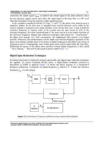
henceforth as SDM) is applied. Figure 7.4 shows the block diagram of a fractional-N
frequency synthesizer. It generates an output frequency f , which is N . F times the reference
2
frequency f . N is the integer
ref
Figure 7.4 A fractional-N frequency synthesizer using a sigma-delta modulator.
Printed from Digital Engineering Library @ McGraw-Hill (www.Digitalengineeringlibrary.com).
Copyright ©2004 The McGraw-Hill Companies. All rights reserved.