
Page 281 - Phase-Locked Loops Design, Simulation, and Applications
P. 281
MIXED-SIGNAL PLL APPLICATIONS PART 2: FRACTIONAL-N FREQUENCY
SYNTHESIZERS Ronald E. Best 167
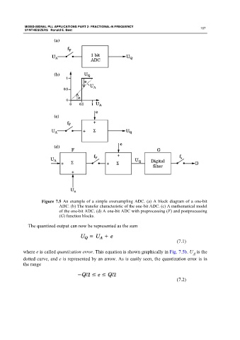
Figure 7.5 An example of a simple oversampling ADC. (a) A block diagram of a one-bit
ADC. (b) The transfer characteristic of the one-bit ADC. (c) A mathematical model
of the one-bit ADC. (d) A one-bit ADC with preprocessing (F) and postprocessing
(G) function blocks.
The quantized output can now be represented as the sum
(7.1)
where e is called quantization error. This equation is shown graphically in Fig. 7.5b. U is the
A
dotted curve, and e is represented by an arrow. As is easily seen, the quantization error is in
the range
(7.2)