Page 68 - Phase-Locked Loops Design, Simulation, and Applications
P. 68

MIXED-SIGNAL PLL ANALYSIS   Ronald E. Best                                              48


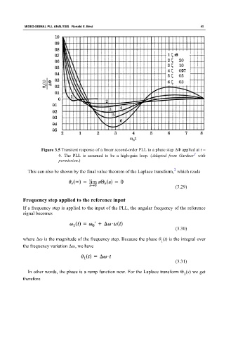
                      Figure 3.5 Transient response of a linear second-order PLL to a phase step ΔΦ applied at t =
                                                                                                  1
                              0. The  PLL  is assumed to be a  high-gain loop. (Adapted from Gardner   with
                              permission.)

                                                                                        3
               This can also be shown by the final value theorem of the Laplace transform,  which reads


                                                                                         (3.29)


             Frequency step applied to the reference input

             If a frequency step is applied to the input of the PLL, the angular frequency of the reference
             signal becomes


                                                                                         (3.30)


             where Δω is the magnitude of the frequency step. Because the phase θ (t) is the integral over
                                                                                 1
             the frequency variation Δω, we have


                                                                                         (3.31)


               In other words, the phase is a ramp function now. For the Laplace transform Θ (s) we get
                                                                                             1
             therefore
   63   64   65   66   67   68   69   70   71   72   73