
Page 33 - Photodetection and Measurement - Maximizing Performance in Optical Systems
P. 33
Amplified Detection Circuitry
26 Chapter Two
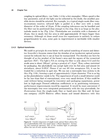
coupling to optical fibers. (see Table 1.2 for a few examples.) When speed is the
key parameter, and all the light can be collected by the diode, the smallest pos-
sible device should be selected. For example, in a typical single-mode fiber com-
munications receiver, infrared light is guided in a fiber core with a mode
diameter of the order of 10mm. If the coupling tolerances can be handled and
the fiber can be positioned close enough to the chip, this is as large as the pho-
todiode needs to be (Fig. 2.5a). Photodiodes are available with a diameter of
25mm; this is small, but the area is still approximately 10 times bigger than
necessary. Although at these small sizes the capacitance is unlikely to reduce
proportionately to area, some gain in improvement is inevitable with smaller
devices.
2.4.3 Optical transforms
We could in principle do even better with optical matching of source and detec-
tor. Liouville’s theorem states that the étendue of an incoherent optical system
cannot be reduced, but it can at least be manipulated. The étendue can here be
thought of as the product of the beam’s area and the square of the numerical
2
aperture (NA ). The light’s NA on exiting the fiber is only about 0.12 and the
2
2
mode area is about 100mm , giving a product of 1.4mm . Now, unless restricted
by packaging, the photodiode can accept light over its full area and almost 2p
2
steradians, about 0.5NA . Hence if we can fill this acceptance NA, it can be
traded for a reduction in spot size. We can use a microoptic lens system to do
this (Fig. 2.5b), forming a spot of approximately 1.6mm diameter. This is as big
as the photodetector needs to be. The capacitance of such a small detector could
be far less than that of conventional, even very small devices. If this could be
used without being swamped by transistor and packaging capacitance, power
lost in high-angle Fresnel reflection coefficients or in positioning tolerances,
performance improvements would be expected. It would be most convenient if
the microoptic lens were integrated permanently with the tiny photodiode, for
illumination from the single-mode fiber or fused onto the fiber end. At least
one company (ALPS Electric) offers lenses and lensed detectors with this
(a) (b)
2
2
2
NA =0.014 NA =0.014 NA =0.5
Area 100mm 2 Area 100mm 2 Area 2.8mm 2
Figure 2.5 Careful alignment of single-mode optical fibers allows the
use of photodiodes with very small areas (<30mm diameter). Increas-
ing the numerical aperture (NA) of the incident light in principle
allows the use of even smaller detectors.
Downloaded from Digital Engineering Library @ McGraw-Hill (www.digitalengineeringlibrary.com)
Copyright © 2004 The McGraw-Hill Companies. All rights reserved.
Any use is subject to the Terms of Use as given at the website.