
Page 36 - Photodetection and Measurement - Maximizing Performance in Optical Systems
P. 36
Amplified Detection Circuitry
Amplified Detection Circuitry 29
6
120 10
106dB Gain¥Frequency = GBW 10 5
Open-loop Voltage Gain (dB) 100 Slope: GBW 10 4 3 2
20Hz
at all frequencies >20Hz
80
-20dB/decade
60
10
40
10
20
0 4MHz 10
1
1 10 100 1k 10k 100k 1M 10M
Frequency (Hz)
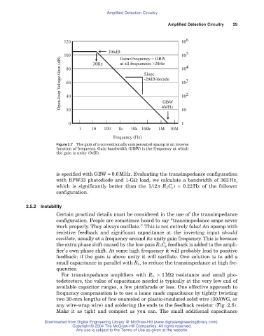
Figure 2.7 The gain of a conventionally compensated opamp is an inverse
function of frequency. Gain bandwidth (GBW) is the frequency at which
the gain is unity (0 dB).
is specified with GBW = 0.6MHz. Evaluating the transimpedance configuration
with BPW33 photodiode and 1-GW load, we calculate a bandwidth of 363Hz,
which is significantly better than the 1/(2p R LC p) = 0.22Hz of the follower
configuration.
2.5.2 Instability
Certain practical details must be considered in the use of the transimpedance
configuration. People are sometimes heard to say “transimpedance amps never
work properly. They always oscillate.” This is not entirely false! An opamp with
resistive feedback and significant capacitance at the inverting input should
oscillate, usually at a frequency around its unity gain frequency. This is because
the extra phase shift caused by the low-pass R LC p feedback is added to the ampli-
fier’s own phase shift. At some high frequency it will probably lead to positive
feedback; if the gain is above unity it will oscillate. One solution is to add a
small capacitance in parallel with R L , to reduce the transimpedance at high fre-
quencies.
For transimpedance amplifiers with R L > 1MW resistance and small pho-
todetectors, the value of capacitance needed is typically at the very low end of
available capacitor ranges, a few picofarads or less. One effective approach to
frequency compensation is to use a home made capacitance by tightly twisting
two 30-mm lengths of fine enameled or plastic-insulated solid wire (30AWG, or
any wire-wrap wire) and soldering the ends to the feedback resistor (Fig. 2.8).
Make it as tight and compact as you can. The small additional capacitance
Downloaded from Digital Engineering Library @ McGraw-Hill (www.digitalengineeringlibrary.com)
Copyright © 2004 The McGraw-Hill Companies. All rights reserved.
Any use is subject to the Terms of Use as given at the website.