
Page 37 - Photodetection and Measurement - Maximizing Performance in Optical Systems
P. 37
Amplified Detection Circuitry
30 Chapter Two
Twisted wire
capacitor
C f
Resistor R L
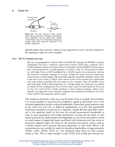
Figure 2.8 The tiny values of extra capaci-
tance often required to stabilize transimped-
ance amplifiers can be made from tightly
twisted wire-wrap wire. Gradually snipping to
length allows the transient response to be
quickly optimized.
should reduce the receiver’s desire to be a generator, and it can be trimmed to
the optimum value in a few seconds.
2.5.3 TRY IT! Twisted wire trick
Set up a transimpedance receiver with an LF356 FET opamp and BPW34 or similar
photodiode. This has a moderate capacitance of about 72pF when unbiased. Use a
10-MW feedback resistor and attach 50mm of doubled, twisted 30AWG (0.25mm diam-
eter) wire-wrap wire as a small capacitor as shown in Fig. 2.8. Illuminate the detec-
tor with light from an LED modulated by a 10-kHz square-wave generator, viewing
the receiver’s transient response on a scope. Trigger the scope from the signal gen-
erator to give a stable display. The transient response should be noticably slower, with
a rise time of the order of 100ms. Now remove 5mm of the twisted wire capacitance
with side-cutters; hopefully this will speed up the response. Take off another 5mm
and look again. With a little experience (i.e., having made two receivers) you will be
an expert at this, needing only two or three snips to get the ideal response. If you go
too far, the result will be a large overshoot in the transient response, which corre-
sponds to an approach to the resonant condition that caused the oscillation. If you do,
make another wire capacitor and try again.
The response obtained in this way may be faster than is needed. Nevertheless,
it is recommended to maximize the amplifier’s speed as described, even if the
eventual application needs a reduced bandwidth. Given that good receivers tend
to get used over and over in different applications, it is felt that bandwidth
restriction should be carried out in a separate, simple RC low-pass filter exter-
nal to the amplifier itself. In this way the actual measurement bandwidth is
clear in each application and rough estimations of noise can be made. A very
useful accessory for photoreceiver development is a set of low-pass filters, wired
on small pieces of copperclad board and fitted with terminals and free wires or
miniature alligator clips (see Chap. 6). By choosing convenient values, such as
a 16-kW resistor and 5 percent tolerance capacitors of 1nF, 10nF, 100nF, 1mF,
measurements can quickly be made at detection bandwidths of approximately
10kHz, 1kHz, 100Hz, 10Hz etc. The standard value from the E24 resistor
series is 16k. This is close enough to the 15.915 that would give decade fre-
Downloaded from Digital Engineering Library @ McGraw-Hill (www.digitalengineeringlibrary.com)
Copyright © 2004 The McGraw-Hill Companies. All rights reserved.
Any use is subject to the Terms of Use as given at the website.