
Page 40 - Photodetection and Measurement - Maximizing Performance in Optical Systems
P. 40
Amplified Detection Circuitry
Amplified Detection Circuitry 33
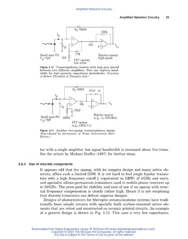
R 100M 180k
f
I p
+
- -
C p 1k0 + V o
Small-area PD 51k Bipolar opamp:
C <5pF 1k0 FET opamp: high-speed
p
low noise
Figure 2.10 Transimpedance receiver with loop gain shared
between two different amplifiers. This can improve band-
width for high parasitic capacitance photodiodes. (Courtesy
of Robert Theobald of Theoptics Ltd.)
R 100M 47nF 1k
f
I p
+
- 10k - V o
C p +
10nF
Bipolar opamp
Small-area PD 100M (e.g., 1 OPA404)
4 /
C <5pF
p
FET opamp
(e.g., OPA111)
Figure 2.11 Another two-opamp transimpedance design.
(Reproduced by permission of Texas Instruments Burr-
Brown.)
tor with a single amplifier, but signal bandwidth is increased about five times.
See the article by Michael Steffes (1997) for further ideas.
2.6.4 Use of discrete components
It appears odd that the opamp, with its complex design and many active ele-
ments, offers such a limited GBW. It is not hard to find single bipolar transis-
tors with a high frequency cutoff f t (equivalent to GBW) of 2GHz and more,
and specialist silicon-germanium transistors used in mobile phone receivers up
to 50GHz. The price paid for stability and ease of use of an opamp with inter-
nal frequency compensation is clearly rather high. Hence it is not surprising
that discrete transistors can deliver superior designs.
Designs of photoreceivers for fiberoptic communications systems have tradi-
tionally been simple circuits with specially built surface-mounted active ele-
ments that are wired and constructed on ceramic printed circuits. An example
of a generic design is shown in Fig. 2.12. This uses a very low capacitance,
Downloaded from Digital Engineering Library @ McGraw-Hill (www.digitalengineeringlibrary.com)
Copyright © 2004 The McGraw-Hill Companies. All rights reserved.
Any use is subject to the Terms of Use as given at the website.