
Page 42 - Photodetection and Measurement - Maximizing Performance in Optical Systems
P. 42
Amplified Detection Circuitry
Amplified Detection Circuitry 35
2.7.2 TRY IT! Resistor choice
Once again, make a transimpedance amplifier based on an FET opamp. Perhaps you
should chose the fastest amplifier from the previous TRY IT!. This time let’s really go
for speed and choose the lowest capacitance photodiode available. Borrow a selection
2
of 100-MW resistors. I used a 1-mm UDT PIN040A photodiode with 15-V reverse bias,
an OPA604 opamp, and six different 100-MW resistors. These range from a 50-mm-
long plate construction device used for 500-VAC operation to a standard axial leaded
0.25W device and a couple of 1 ¥ 2-mm chip resistors.
Illuminate the photodiode with a red LED connected to a square-wave generator,
but keep it far enough away not to couple it electrically. This is often visible as greatly
enhanced flanks on the received square wave. This is a spurious coupling via the capac-
itance between LED leads and photodiode leads and gives a high-pass characteristic
coupling response. A 100-mm glass or grounded metal tube with an LED and photo-
diode lodged in each end can be used to increase optical coupling efficiency. Alterna-
tively, a fiber could be used, albeit with a lot more work.
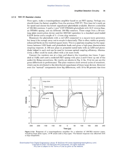
Connect the resistors one at a time and observe the transition rise times. I oper-
ated at 5kHz and used a socketed FET opamp with pins 2 and 6 bent up out of the
socket for flying connections. My results are shown in Fig. 2.13a. First we can see the
gross differences in performance. The plate resistors show several cycles of overshoot,
which can be attributed to the distributed capacitance of these large devices. However
even the “normal” components show big differences, with 10 to 90 percent rise time
10
Large plate
8
Medium plate
Chip
6
4
Intensity 2 1/4W axial
0
-2
-4
-6
-250 -200 -150 -100 -50 0 50 100 150 200 250
Time (ms)
Figure 2.13a Response of a transimpedance amplifier for a selection of 100-MW resistor types,
including large plate types, 1/4-W axials and a chip types. The fastest response was obtained with
a chip component.
Downloaded from Digital Engineering Library @ McGraw-Hill (www.digitalengineeringlibrary.com)
Copyright © 2004 The McGraw-Hill Companies. All rights reserved.
Any use is subject to the Terms of Use as given at the website.