
Page 46 - Photodetection and Measurement - Maximizing Performance in Optical Systems
P. 46
Amplified Detection Circuitry
Amplified Detection Circuitry 39
C f
R c
R f C c
I p
+ A V o
-
Figure 2.17 The parasitic capacitance may
be partially compensated using the addi-
tional RC network. Ideally R c C c = R f C f , but
make R c a single-turn trimpot and adjust
for optimum.
4.5 Over-comp.
4.0
3.5 Optimum
3.0
Voltage (V) 2.0 Under-comp.
2.5
1.5
1.0
0.5
0.0
-0.5
-1.0
-1.5
-200 -150 -100 -50 0 50 100 150 200
Time (ms)
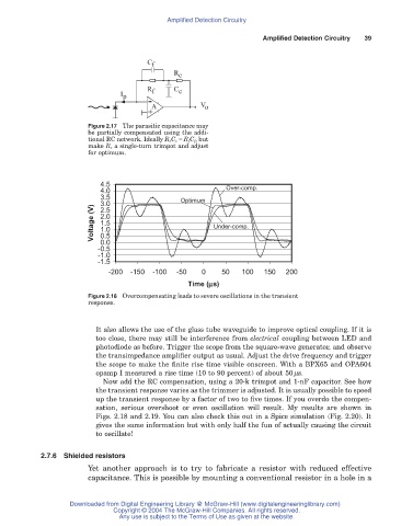
Figure 2.18 Overcompensating leads to severe oscillations in the transient
response.
It also allows the use of the glass tube waveguide to improve optical coupling. If it is
too close, there may still be interference from electrical coupling between LED and
photodiode as before. Trigger the scope from the square-wave generator, and observe
the transimpedance amplifier output as usual. Adjust the drive frequency and trigger
the scope to make the finite rise time visible onscreen. With a BPX65 and OPA604
opamp I measured a rise time (10 to 90 percent) of about 50ms.
Now add the RC compensation, using a 20-k trimpot and 1-nF capacitor. See how
the transient response varies as the trimmer is adjusted. It is usually possible to speed
up the transient response by a factor of two to five times. If you overdo the compen-
sation, serious overshoot or even oscillation will result. My results are shown in
Figs. 2.18 and 2.19. You can also check this out in a Spice simulation (Fig. 2.20). It
gives the same information but with only half the fun of actually causing the circuit
to oscillate!
2.7.6 Shielded resistors
Yet another approach is to try to fabricate a resistor with reduced effective
capacitance. This is possible by mounting a conventional resistor in a hole in a
Downloaded from Digital Engineering Library @ McGraw-Hill (www.digitalengineeringlibrary.com)
Copyright © 2004 The McGraw-Hill Companies. All rights reserved.
Any use is subject to the Terms of Use as given at the website.