
Page 48 - Photodetection and Measurement - Maximizing Performance in Optical Systems
P. 48
Amplified Detection Circuitry
Amplified Detection Circuitry 41
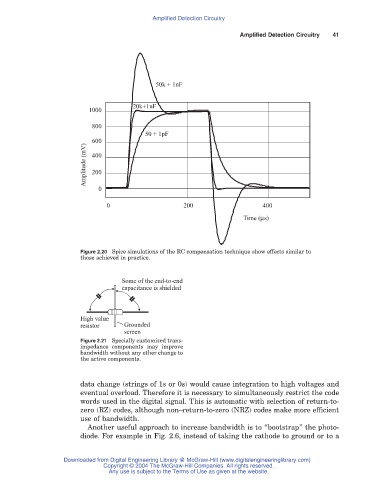
50k + 1nF
20k+1nF
1000
800
50 + 1pF
600
Amplitude (mV) 400
200
0
0 200 400
Time (μs)
Figure 2.20 Spice simulations of the RC compensation technique show effects similar to
those achieved in practice.
Some of the end-to-end
capacitance is shielded
High value
resistor Grounded
screen
Figure 2.21 Specially customized trans-
impedance components may improve
bandwidth without any other change to
the active components.
data change (strings of 1s or 0s) would cause integration to high voltages and
eventual overload. Therefore it is necessary to simultaneously restrict the code
words used in the digital signal. This is automatic with selection of return-to-
zero (RZ) codes, although non–return-to-zero (NRZ) codes make more efficient
use of bandwidth.
Another useful approach to increase bandwidth is to “bootstrap” the photo-
diode. For example in Fig. 2.6, instead of taking the cathode to ground or to a
Downloaded from Digital Engineering Library @ McGraw-Hill (www.digitalengineeringlibrary.com)
Copyright © 2004 The McGraw-Hill Companies. All rights reserved.
Any use is subject to the Terms of Use as given at the website.