
Page 34 - Photodetection and Measurement - Maximizing Performance in Optical Systems
P. 34
Amplified Detection Circuitry
Amplified Detection Circuitry 27
improvement in mind. Similar gains could be obtained using NA-transforming
fiber tapers.
Another application where lens systems are important is a free-space system
such as burglar alarm systems, industrial control beam-sensors, and terrestrial
and intersatellite free-space communication systems. In these cases there is
little divergence in the incident light as it arrives, and it is spread beyond the
area of any conventional photodetector. Hence a collection lens can give large
signal increases without additional noise. The only drawback is that the reduced
acceptance angle of the lensed receiver requires more accurate pointing and
mechanical stability or active direction control. For intersatellite communica-
tions, much system complexity comes from the scanned acquisition of the trans-
mitted signal at a relatively wide receiver acceptance angle, followed by active
focus control to optimize received power. Where the apparent light source is
large and indeterminate in arrival direction, for example in a domestic diffuse
light communication system, it may be more efficient to use large detectors
(solar cells have the lowest cost per unit area) or detectors made to “look” larger
by embedding in a transparent hemisphere of high refractive index.
2.5 Transimpedance Amplifier
2.5.1 Why so good?
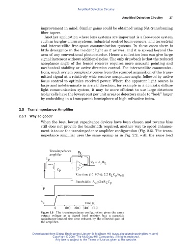
When the best, lowest capacitance devices have been chosen and reverse bias
still does not provide the bandwidth required, another way to speed enhance-
ment is to use the transimpedance amplifier configuration (Fig. 2.6). The trans-
impedance amplifier uses the same opamp as in Fig. 2.2, with the same load
Transimpedance R
amplifier L
I p
V o = -I R
p L
+ A
-
C p
Rise time (10–90%): 2.2 R C /A eff
L p
p
Bandwidth: A eff /2 R C
L p
I p
V o Time (s)
0 1RC 2RC 3RC 4RC
Figure 2.6 The transimpedance configuration gives the same
output voltage as a biased load resistor, but a parasitic
capacitance-limited rise time reduced by the effective gain of
the amplifier.
Downloaded from Digital Engineering Library @ McGraw-Hill (www.digitalengineeringlibrary.com)
Copyright © 2004 The McGraw-Hill Companies. All rights reserved.
Any use is subject to the Terms of Use as given at the website.