
Page 90 - Pipeline Rules of Thumb Handbook
P. 90
Construction 77
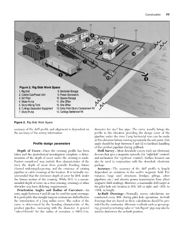
Figure 2. Rig Side Work Space
accuracy of the drill profile and alignment is dependent on diameter for steel line pipe. The curve usually brings the
the accuracy of the survey information. profile to the elevation providing the design cover of the
pipeline under the river. Long horizontal runs can be made
at this elevation before curving up towards the exit point. Exit
Profile design parameters angle should be kept between 5 and 12 to facilitate handling
of the product pipeline during pullback.
Depth of Cover—Once the crossing profile has been Drill Survey—Most downhole survey tools are electronic
taken and the geotechnical investigation complete, a deter- devices that give a magnetic azimuth (for “right/left” control)
mination of the depth of cover under the crossing is made. and inclination (for “up/down” control). Surface locators can
Factors considered may include flow characteristics of the also be used in conjunction with the downhole electronic
river, the depth of scour from periodic flooding, future package.
channel widening/deepening, and the existence of existing Accuracy—The accuracy of the drill profile is largely
pipeline or cable crossings at the location. It is normally rec- dependent on variations in the earth’s magnetic field. For
ommended that the minimum depth of cover be 20ft. under instance, large steel structures (bridges, pilings, other
the lowest section of the crossing. While 20ft. is a recom- pipelines, etc.) and electric power transmission lines affect
mended depth of cover on a river crossing, crossings of other magnetic field readings. However, a reasonable drill target at
obstacles may have differing requirements. the pilot hole exit location is 10ft. left or right, and -10ft. to
Penetration Angles and Radius of Curvature—An +30ft. in length.
entry angle between 8 and 20 can be used for most crossings. As-Built Drawings—Normally, survey calculations are
It is preferable that straight tangent sections are drilled before conducted every 30ft. during pilot hole operations. As-built
the introduction of a long radius curve. The radius of the drawings that are based on these calculations should be pro-
curve is determined by the bending characteristic of the vided by the contractor. Alternate methods such as gyroscop-
product pipeline, increasing with the diameter. A general ing, ground penetrating radar or “intelligent” pigs may also be
“rule-of-thumb” for the radius of curvature is 100ft./1-in. used to determine the as-built position.