
Page 92 - Pipeline Rules of Thumb Handbook
P. 92
Construction 79
to estimate the in situ relative density of cohesionless soils. recommendations are meant to be used only as a starting
Some geotechnical firms will conduct these penetration tests point in the design. It is recommended that in the final design,
in cohesive materials and rock, and to a lesser extent, the con- specific stresses be calculated and compared with allowable
sistency of cohesive soils and the hardness of rock can be limits.
determined.
Thinwalled “Shelby” Tube Sampling—Most geotech-
nical firms prefer to use a Thinwalled Tube Sampling method
for obtaining samples of cohesive materials. These tests are
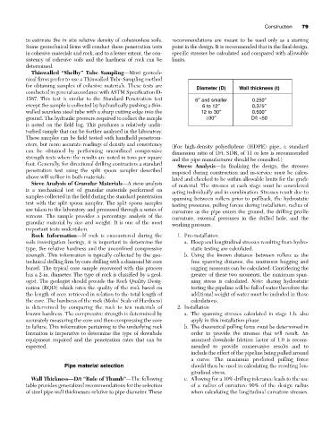
Diameter (D) Wall thickness (t)
conducted in general accordance with ASTM Specification D-
1587. This test is similar to the Standard Penetration test 6≤ and smaller 0.250≤
except the sample is collected by hydraulically pushing a thin- 6 to 12≤ 0.375≤
walled seamless steel tube with a sharp cutting edge into the 12 to 30≤ 0.500≤
ground. The hydraulic pressure required to collect the sample ≥30≤ D/t <50
is noted on the field log. This produces a relatively undis-
turbed sample that can be further analyzed in the laboratory.
These samples can be field tested with handheld penetrom-
eters, but more accurate readings of density and consistency (For high-density polyethylene (HDPE) pipe, a standard
can be obtained by performing unconfined compressive dimension ratio of D/t, SDR, of 11 or less is recommended
strength tests where the results are noted in tons per square and the pipe manufacturer should be consulted.)
foot. Generally, for directional drilling contractors a standard Stress Analysis—In finalizing the design, the stresses
penetration test using the split spoon sampler described imposed during construction and in-service must be calcu-
above will suffice in both materials. lated and checked to be within allowable limits for the grade
Sieve Analysis of Granular Materials—A sieve analysis of material. The stresses at each stage must be considered
is a mechanical test of granular materials performed on acting individually and in combination. Stresses result due to
samples collected in the field during the standard penetration spanning between rollers prior to pullback, the hydrostatic
test with the split spoon sampler. The split spoon samples testing pressures, pulling forces during installation, radius of
are taken to the laboratory and processed through a series of curvature as the pipe enters the ground, the drilling profile
screens. The sample provides a percentage analysis of the curvature, external pressures in the drilled hole, and the
granular material by size and weight. It is one of the most working pressure.
important tests undertaken.
Rock Information—If rock is encountered during the 1. Pre-installation
soils investigation borings, it is important to determine the a. Hoop and longitudinal stresses resulting from hydro-
type, the relative hardness and the unconfined compressive static testing are calculated.
strength. This information is typically collected by the geo- b. Using the known distance between rollers as the
technical drilling firm by core drilling with a diamond bit core free spanning distance, the maximum hogging and
barrel. The typical core sample recovered with this process sagging moments can be calculated. Considering the
has a 2-in. diameter. The type of rock is classified by a geol- greater of these two moments, the maximum span-
ogist. The geologist should provide the Rock Quality Desig- ning stress is calculated. Note: during hydrostatic
nation (RQD) which rates the quality of the rock based on testing the pipeline will be full of water therefore the
the length of core retrieved in relation to the total length of additional weight of water must be included in these
the core. The hardness of the rock (Mohs’ Scale of Hardness) calculations.
is determined by comparing the rock to ten materials of 2. Installation
known hardness. The compressive strength is determined by a. The spanning stresses calculated in stage 1.b. also
accurately measuring the core and then compressing the core apply in this installation phase.
to failure. This information pertaining to the underlying rock b. The theoretical pulling force must be determined in
formation is imperative to determine the type of downhole order to provide the stresses that will result. An
equipment required and the penetration rates that can be assumed downhole friction factor of 1.0 is recom-
expected. mended to provide conservative results and to
include the effect of the pipeline being pulled around
a curve. The maximum predicted pulling force
Pipe material selection should then be used in calculating the resulting lon-
gitudinal stress.
Wall Thickness—D/t “Rule of Thumb”—The following c. Allowing for a 10% drilling tolerance leads to the use
table provides generalized recommendations for the selection of a radius of curvature 90% of the design radius
of steel pipe wall thicknesses relative to pipe diameter. These when calculating the longitudinal curvature stresses.