
Page 97 - Pipeline Rules of Thumb Handbook
P. 97
84 Pipeline Rules of Thumb Handbook
Steel pipe design
The maximum allowable design pressure stress will depend where P = Design pressure, lb/in. 2
2
upon the intended service for the pipeline. S = Specified minimum yield strength, lb/in. (see
Pipelines to be used for transporting liquid petroleum are Table 1)
covered by ANSI/ASME B31.4—“Liquid Petroleum Trans- t = Nominal wall thickness, in.
portation Piping Systems.” Pipelines used for transporting gas D = Nominal outside diameter, in.
are covered by ANSI/ASME B31.8—“Gas Transmission and F = Design factor (see Table 2)
Distribution Systems.” E = Longitudinal joint factor (see Table 3)
Pipelines which must be operated in compliance with the T = Temperature derating factor (see Table 4)
Federal Pipeline Safety Regulations will also need to comply
with the applicable parts of these regulations: Part 192 for gas Class location definitions may be obtained from p. 192.111 of
transportation systems, and Part 195 for liquid transportation Part 192 of the Federal Pipeline Safety Regulations.
systems. A typical calculation is as follows:
Pipe: 16≤ OD ¥ 0.250≤ wt API 5LX X52 ERW
Location: Class 1, therefore F = 0.72 (see Table 2)
Gas pipelines—ANSI/ASME B31.8
Temperature: 90°F, Temp. factor T = 1 (see Table 4)
Joint Factor: E = 1.0 (see Table 3)
The maximum allowable pressure is calculated by the
following equation:
.
1
.
,
P = (2 ¥ 52 000 ¥ 0 250 16 0 ) ¥ 0 72. ¥ ¥ 1
2
.
P = (2 St D) ¥ F E T P = 1 170 lb in gauge
,
¥
¥
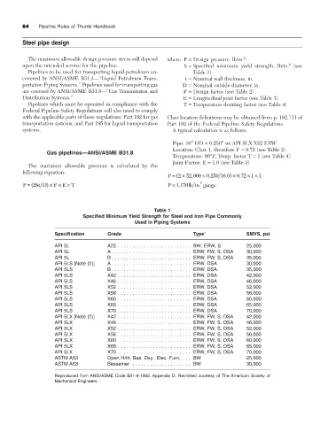
Table 1
Specified Minimum Yield Strength for Steel and Iron Pipe Commonly
Used in Piping Systems
Specification Grade Type 1 SMYS, psi
API 5L A25 . . . . . . . . . . . . . . . . . . . . . . . . . BW, ERW, S 25,000
API 5L A . . . . . . . . . . . . . . . . . . . . . . . . . . . ERW, FW, S, DSA 30,000
API 5L B . . . . . . . . . . . . . . . . . . . . . . . . . . . ERW, FW, S, DSA 35,000
API 5LS [Note (2)] A . . . . . . . . . . . . . . . . . . . . . . . . . . . ERW, DSA 30,000
API 5LS B . . . . . . . . . . . . . . . . . . . . . . . . . . . ERW, DSA 35,000
API 5LS X42 . . . . . . . . . . . . . . . . . . . . . . . . . ERW, DSA 42,000
API 5LS X46 . . . . . . . . . . . . . . . . . . . . . . . . . ERW, DSA 46,000
API 5LS X52 . . . . . . . . . . . . . . . . . . . . . . . . . ERW, DSA 52,000
API 5LS X56 . . . . . . . . . . . . . . . . . . . . . . . . . ERW, DSA 56,000
API 5LS X60 . . . . . . . . . . . . . . . . . . . . . . . . . ERW, DSA 60,000
API 5LS X65 . . . . . . . . . . . . . . . . . . . . . . . . . ERW, DSA 65,000
API 5LS X70 . . . . . . . . . . . . . . . . . . . . . . . . . ERW, DSA 70,000
API 5LX [Note (2)] X42 . . . . . . . . . . . . . . . . . . . . . . . . . ERW, FW, S, DSA 42,000
API 5LX X46 . . . . . . . . . . . . . . . . . . . . . . . . . ERW, FW, S, DSA 46,000
API 5LX X52 . . . . . . . . . . . . . . . . . . . . . . . . . ERW, FW, S, DSA 52,000
API 5LX X56 . . . . . . . . . . . . . . . . . . . . . . . . . ERW, FW, S, DSA 56,000
API 5LX X60 . . . . . . . . . . . . . . . . . . . . . . . . . ERW, FW, S, DSA 60,000
API 5LX X65 . . . . . . . . . . . . . . . . . . . . . . . . . ERW, FW, S, DSA 65,000
API 5LX X70 . . . . . . . . . . . . . . . . . . . . . . . . . ERW, FW, S, DSA 70,000
ASTM A53 Open Hrth. Bas. Oxy., Elec. Furn. . . . BW 25,000
ASTM A53 Bessemer . . . . . . . . . . . . . . . . . . . . BW 30,000
Reproduced from ANSI/ASME Code B31-8-1982, Appendix D. Reprinted courtesy of The American Society of
Mechanical Engineers.