
Page 99 - Pipeline Rules of Thumb Handbook
P. 99
86 Pipeline Rules of Thumb Handbook
Liquid pipelines—ANSI/ASME B31.4 Note: Refer to p. 195.106 of Part 195 Federal Pipeline
Safety Regulations for design factors to be used on offshore
The internal design pressure is determined by using the risers and platform piping and cold worked pipe.
following formula: A typical calculation of the internal design pressure is as
follows:
P = (2 St D) ¥ E F
¥
2
where P = Internal design pressure, lb/in. gauge Pipe: 26≤ OD ¥ 0.3125≤ wt API 5LX X52 ERW
2
S = Specified minimum yield strength, lb/in. (see Weld joint factor E = 1.0 (see Table 6)
Table 5) Design factor F = 0.72
t = Nominal wall thickness, in.
D = Nominal outside diameter of the pipe, in.
.
,
E = Weld joint factor (see Table 6) P = (2 ¥ 52 000 ¥ 0 3125 26 ) ¥¥1 0 72.
2
F = Design factor of 0.72 P = 900 lb in gauge
.
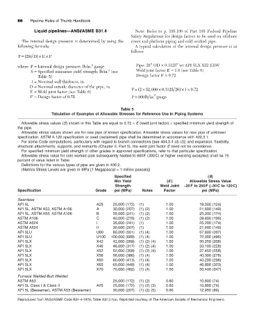
Table 5
Tabulation of Examples of Allowable Stresses for Reference Use in Piping Systems
Allowable stress values (S) shown in this Table are equal to 0.72 ¥ E (weld joint factor) ¥ specified minimum yield strength of
the pipe.
Allowable stress values shown are for new pipe of known specification. Allowable stress values for new pipe of unknown
specification, ASTM A 120 specification or used (reclaimed) pipe shall be determined in accordance with 402.3.1.
For some Code computations, particularly with regard to branch connections [see 404.3.1 (d) (3)] and expansion, flexibility,
structural attachments, supports, and restraints (Chapter II, Part 5), the weld joint factor E need not be considered.
For specified minimum yield strength of other grades in approved specifications, refer to that particular specification.
Allowable stress value for cold worked pipe subsequently heated to 600F (300C) or higher (welding excepted) shall be 75
percent of value listed in Table.
Definitions for the various types of pipe are given in 400.2.
(Metrics Stress Levels are given in MPa [1 Megapascal = 1 million pascals])
Specified (S)
Min Yield (E ) Allowable Stress Value
Strength Weld Joint -20F to 250F (-30C to 120C)
Specification Grade psi (MPa) Notes Factor psi (MPa)
Seamless
API 5L A25 25,000 (172) (1) 1.00 18,000 (124)
API 5L, ASTM A53, ASTM A106 A 30,000 (207) (1) (2) 1.00 21,600 (149)
API 5L, ASTM A53, ASTM A106 B 35,000 (241) (1) (2) 1.00 25,200 (174)
ASTM A106 C 40,000 (278) (1) (2) 1.00 28,800 (199)
ASTM A524 I 35,000 (241) (1) 1.00 25,200 (174)
ASTM A524 II 30,000 (207) (1) 1.00 21,600 (149)
API 5LU U80 80,000 (551) (1) (4) 1.00 57,600 (397)
API 5LU U100 100,000 (689) (1) (4) 1.00 72,000 (496)
API 5LX X42 42,000 (289) (1) (2) (4) 1.00 30,250 (208)
API 5LX X46 46,000 (317) (1) (2) (4) 1.00 33,100 (228)
API 5LX X52 52,000 (358) (1) (2) (4) 1.00 37,450 (258)
API 5LX X56 56,000 (386) (1) (4) 1.00 40,300 (278)
API 5LX X60 60,000 (413) (1) (4) 1.00 43,200 (298)
API 5LX X65 65,000 (448) (1) (4) 1.00 46,800 (323)
API 5LX X70 70,000 (482) (1) (4) 1.00 50,400 (347)
Furnace Welded-Butt Welded
ASTM A53 25,000 (172) (1) (2) 0.60 10,800 (74)
API 5L Class I & Class II A25 25,000 (172) (1) (2) (3) 0.60 10,800 (74)
API 5L (Bessemer), ASTM A53 (Bessemer) 30,000 (207) (1) (2) (5) 0.60 12,950 (89)
Reproduced from ANSI/ASME Code B31-4-1979, Table 402.3.1(a). Reprinted courtesy of The American Society of Mechanical Engineers.