
Page 219 - Pipelines and Risers
P. 219
192 Chapter 12
The true tension is an integration of stress over the cross-section of the steel wall. In deep
water, Tp usually are greater than Ta. The result of this is that Te becomes negative and the
pipe section, as a beam, will be in compression instead of tension. The force T, is a function
of the water depth so Te will always be positive at the sea surface and be positive or negative
at the seabed depending on the relationship between T, and Tp.
12.4.5 Curvature in Overbend
The part of the pipeline that is supported by the layramp that are made up of the rollers placed
on the stinger and the vessel will have the same curvature as the layramp. A target for
installation analysis is to find the best layramp configuration for the pipeline that is going to
be installed.
The layramp consists of the lay-vessel and the stinger. The function of the layramp is to
provide a curved support with an overall radius of curvature. The result of this is a bending
moment in the pipeline and strain. This curve is created by placing out a number of rollers at
the barge and at the stinger. The location of these rollers depends on which radius of
curvature that is needed to control the overbend-strain in the pipeline within acceptable level.
The configuration and curvature of the pipe section are displacement controlled at the stinger.
This means that the pipeline displacement is governed by the stinger and roller properties.
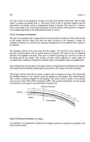
The stinger and the vessel do not create a support with a constant curvature. This means that
the bending moment is not constant along the pipeline on the stinger. The rollers/supports
don’t create a continuos support for the pipeline. The result of this is peaks in the moment
level at every roller NOU (1974) and Igland (1997). The moment distribution over the stinger
will therefore in principle be like illustrated in Figurel2.10.
Moment distribution
Pipeline
Figure 12.10 Moment distribution over stinger.
It is therefore very important to represent the stinger geometry as accurate as possible in the
finite element model.