
Page 220 - Pipelines and Risers
P. 220
Imtallaiion Design 193
12.4.6 Strain Concentration and Residual Strain
Offshore pipelines are usually coated with concrete in order to counteract buoyancy and
through this ensure on-bottom stability. The pipeline is also covered with corrosion coating.
The effect of the coating weight may be easily accounted for in analysis. The concrete also
has an effect on the pipe stiffness. The concrete has high compressive strength and low tensile
strength. There is a discontinuity in the concrete coating on the pipeline. The most important
effect of this is the occurrence of strain concentration at field joints during bending of the
pipeline. The effect the concrete has on stiffness and strain in the pipeline is not accounted for
in the model.
During installation, the pipeline is exposed to plastic strains when the pipeline passes over the
stinger and exceeding a certain curvature. This means that the pipeline leaves the stinger with
a residual curvature. When passing the inflection point, the bending of the pipeline is
reversed; i.e. the residual curvature has to be overcome. This occurs partially through bending
and partially through twisting. The pipeline will have residual strain when it is installed at the
seabed because it has been exposed to plastic strains (Eindal et al. 1995).
12.4.7 Rigid Section in the Pipeline
A valve has bigger outer diameter and is more rigid than the adjacent pipeline. Both these
facts have an effect on the pipeline response. The result of a more rigid section in the pipeline
is a higher bending moment. The increase in bending moment induces higher strains in the
adjacent pipeline. The increase in bending moment because of the fact that the valve is more
rigid will occur both in overbend and in the sagbend. To reduce the bending moment in the
sagbend a higher lay tension can be applied to the pipeline. The lay tension will then have to
be higher than normal as long as the valve is located in the sagbend.
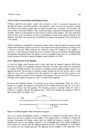
Reducing the bending moment in overbend can be more complicated. When the valve is
located at a support, the pipeline configuration will be lifted locally because the valve has a
bigger outer radius than the pipeline. The bending moment is greatest when the valve is
located at a support, because the pipeline then is lifted. The distance the pipeline is lifted is
here named offset, see Figure 12.11.
Valve
Pipe
Offset
Figure 12.11 Offset of pipeline when valve located at support.
One way to reduce the bending moment in overbend is to increase the stinger radius. The lay
tension for the entire pipeline will be higher if the stinger radius is increased to reduce the
moment. Increasing the stinger radius may not reduce the moment enough in overbend.
Keeping the strain in the adjacent pipeline at an acceptable level may require strapping of
wood timber (or similar) onto the adjacent pipeline sections. This strapping of wood timber
(or similar) are here named tapering. The tapering can be strapped to the underside of the