
Page 221 - Pipelines and Risers
P. 221
194 Chapter I2
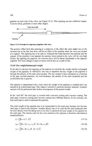
pipeline on each side of the valve, see Figure 12.12. This tapering can have different shapes.
It can be linear, parabolic or have other shapes.
Tapering length
4 *
1
Tapering f
Figure 12.12 Principle for tapering of pipeline with valve.
The positive effect from this tapering is a reduction of the effect the outer radius has on the
moment due to the fact that there will be an offset of the pipeline when the valve are located
at a support. The tapering has to be able to withstand the loads between the pipeline and the
support. If the pipeline is not tapered, the reaction force normal to the valve will be very high
locally. By tapering the pipeline, the reaction force will be better distributed to the adjacent
supports. The local change in pipe curvature will be less as a result of this.
12.4.8 Dry WeighUSubmerged weight
To be able to calculate the response of the pipeline we need the dry weight and the submerged
weight of the pipeline. In ABAQUS, one way to represent the dry weight of the pipeline is
through the density of the steel cross-section. The dry weight is then calculated as a function
of the pipe external diameter, the wall thickness, the density of the steel (material) and the
acceleration due to gravity.
The pipeline is represented with a mass when the weight of the pipeline is modeled this way
instead of as a distributed load. This makes it possible to perform dynamic analysis. Dynamic
analysis will be performed after further development of the present model.
In the “real life” the steel pipe is covered with corrosion coating and concrete coating. The
steel pipe, corrosion coating and concrete coating have different density. In the analyses, the
bare steel pipe is used to represent the pipeline.
The total weight of the pipeline has to be represented by the steel pipe because just the bare
steel pipe is used in the analyses. Another density has to be used for the steel (material) than
the steel density from the design data to be able to represent the total weight of the pipeline by
the steel pipe. The density used for the cross-section to the pipeline is therefore calculated as
explained below.
A, =r((Di+2t,)2-D:) (12.13)
4
(12.14)
(12.15)