
Page 226 - Pipelines and Risers
P. 226
Installation Design 199
pipelay where the pipe is subject to its submerged weight and axial tension. The pre-curved
overbend pipe represents a pipe that has been plastically deformed on the stinger to give 0.1%
residual strain while the pre-curved underbend pipe illustrates a naturally stable case from the
gravitational viewpoint. The reference system has its x-axis origin at the fixed point with
positive direction towards right in the figures below and positive z is upward.
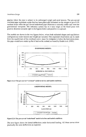
The models are shown in the two figures below, where both unloaded shapes and equilibrium
configurations under tension and weight are included. One important observation can be made
from the equilibrium of the overbend curve: since the midpoint is below the horizontal plane,
this pipe would have ended up flat if laid on the seabed, as found by Endal et al. (1995).
ei1-1
OVERBEND MODEL
a
a 0
Y
i -100
-200
0 200 400 600 800 1000 1200 1400
HORIZONTAL DISTANCE (m)
-Unloaded -Weight + Tension
Figure 12.13 The pre-curved “overbend” model in its free and loaded conditions.
UNDERBEND MODEL
0 -150
5 -200
-250
a -300
-350
0 200 400 600 800 TO00 1200 1401
ELEVATION (m)
-Unloaded -Weight + Tension
Figure12.14 The pre-curved “underbend” model in its free and loaded conditions.
The next figure shows the lateral deflections under horizontal loading. All three curves show
practically the same deflections as expected.