
Page 227 - Pipelines and Risers
P. 227
200 Chapter I2
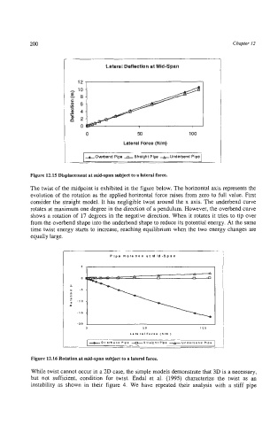
I Lateral Deflection at Mid-Span
0 50 100
Lateral Force (N/m)
+Owbend Pipe &Straight Pipe +Underbend Pipe
Figure 12.15 Displacement at mid-span subject to a lateral force.
The twist of the midpoint is exhibited in the figure below. The horizontal axis represents the
evolution of the rotation as the applied horizontal force raises from zero to full value. First
consider the straight model. It has negligible twist around the x axis. The underbend curve
rotates at maximum one degree in the direction of a pendulum. However, the overbend curve
shows a rotation of 17 degrees in the negative direction. When it rotates it tries to tip over
from the overbend shape into the underbend shape to reduce its potential energy. At the same
time twist energy starts to increase, reaching equilibrium when the two energy changes are
equally large.
I Plpe Rolation at Mid-Span
I 5~ 1
- 0
- .5
0 -
5
; -10
a
-1 5
-20
0 50 100
L.1. ral Fore. (Nlm )
-Overbend Pipe -SllaiphlPipe -Underbend Pipe
Figure 12.16 Rotation at mid-span subject to a laterai force.
While twist cannot occur in a 2D case, the simple models demonstrate that 3D is a necessary,
but not sufficient, condition for twist. Endal et al. (1995) characterize the twist as an
instability as shown in their figure 4. We have repeated their analysis with a stiff pipe