
Page 232 - Pipelines and Risers
P. 232
Installation Design 205
c Concentrated force
Fixed point
Stinger ’
Sea bed
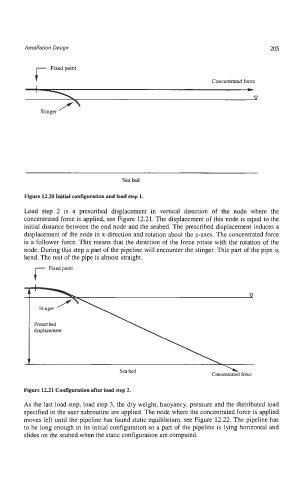
Figure 12.20 Initial configuration and load step 1.
Load step 2 is a prescribed displacement in vertical direction of the node where the
concentrated force is applied, see Figure 12.21. The displacement of this node is equal to the
initial distance between the end node and the seabed. The prescribed displacement induces a
displacement of the node in x-direction and rotation about the z-axes. The concentrated force
is a follower force. This means that the direction of the force rotate with the rotation of the
node. During this step a part of the pipeline will encounter the stinger. This part of the pipe is
bend. The rest of the pipe is almost straight.
f
Fixed point
\
Sea bed
Concentrated force
Figure 12.21 Configuration after load step 2.
As the last load step, load step 3, the dry weight, buoyancy, pressure and the distributed load
specified in the user subroutine are applied. The node where the concentrated force is applied
moves left until the pipeline has found static equilibrium, see Figure 12.22. The pipeline has
to be long enough in its initial configuration so a part of the pipeline is lying horizontal and
slides on the seabed when the static configuration are computed.