
Page 233 - Pipelines and Risers
P. 233
206 Chapter I2
r
Fixed point
r
Sea
bed
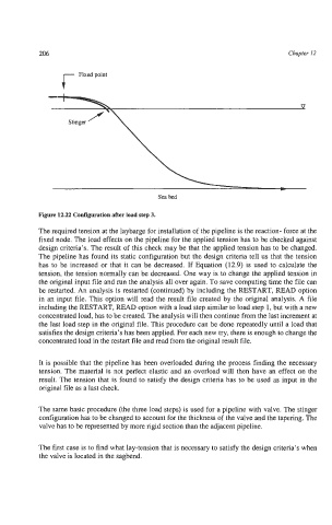
Figure 12.22 Configuration after load step 3.
The required tension at the laybarge for installation of the pipeline is the reaction- force at the
fixed node. The load effects on the pipeline for the applied tension has to be checked against
design criteria’s. The result of this check may be that the applied tension has to be changed.
The pipeline has found its static configuration but the design criteria tell us that the tension
has to be increased or that it can be decreased. If Equation (12.9) is used to calculate the
tension, the tension normally can be decreased. One way is to change the applied tension in
the original input file and run the analysis all over again. To save computing time the file can
be restarted. An analysis is restarted (continued) by including the RESTART, READ option
in an input file. This option will read the result file created by the original analysis. A file
including the RESTART, READ option with a load step similar to load step 1, but with a new
concentrated load, has to be created. The analysis will then continue from the last increment at
the last load step in the original file. This procedure can be done repeatedly until a load that
satisfies the design criteria’s has been applied. For each new try, there is enough to change the
concentrated load in the restart file and read from the original result file.
It is possible that the pipeline has been overloaded during the process finding the necessary
tension. The material is not perfect elastic and an overload will then have an effect on the
result. The tension that is found to satisfy the design criteria has to be used as input in the
original file as a last check.
The same basic procedure (the three load steps) is used for a pipeline with valve. The stinger
configuration has to be changed to account for the thickness of the valve and the tapering. The
valve has to be represented by more rigid section than the adjacent pipeline.
The first case is to find what lay-tension that is necessary to satisfy the design criteria’s when
the valve is located in the sagbend.