
Page 231 - Pipelines and Risers
P. 231
204 Chapter 12
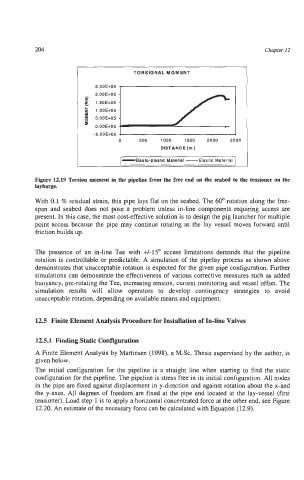
TORSIONAL MOMENT
2.50E+06
-5.OOE+05
0 500 1000 1500 2000 2500
DlSTANCE(m)
-Elasto-plastic Material -Elastic Material
Figure 12.19 Torsion moment in the pipeline from the free end on the seabed to the tensioner on the
laybarge.
With 0.1 % residual strain, this pipe lays flat on the seabed. The 60" rotation along the free-
span and seabed does not pose a problem unless in-line components requiring access are
present. In this case, the most cost-effective solution is to design the pig launcher for multiple
point access because the pipe may continue rotating as the lay vessel moves forward until
friction builds up.
The presence of an in-line Tee with +/-15O access limitations demands that the pipeline
rotation is controllable or predictable. A simulation of the pipelay process as shown above
demonstrates that unacceptable rotation is expected for the given pipe configuration. Further
simulations can demonstrate the effectiveness of various corrective measures such as added
buoyancy, pre-rotating the Tee, increasing tension, current monitoring and vessel offset. The
simulation results will allow operators to develop contingency strategies to avoid
unacceptable rotation, depending on available means and equipment.
12.5 Finite Efement Analysis Procedure for Installation of In-line Valves
12.5.1 Finding Static Configuration
A Finite Element Analysis by Martinsen (1998), a M.Sc. Thesis supervised by the author, is
given below.
The initial configuration for the pipeline is a straight line when starting to find the static
configuration for the pipeline. The pipeline is stress free in its initial configuration. All nodes
in the pipe are fixed against displacement in y-direction and against rotation about the x-and
the y-axes. All degrees of freedom are fixed at the pipe end located at the lay-vessel (first
tensioner). Load step I is to apply a horizontal concentrated force at the other end, see Figure
12.20. An estimate of the necessary force can be caIculated with Equation (12.9).