
Page 234 - Pipelines and Risers
P. 234
Installation Design 207
The second case is to place the valve at the support on the stinger that results in highest strains
for a pipeline without valve.
A third case can be to place the valve at the support where the distance to the adjacent
supports is greatest.
Analyses with different lengths and types of tapering have to be performed for the cases
where the valve is located at the stinger. The result of this is that a lot of analyses have to be
performed for each case. This is the reason for making a spreadsheet that computes some of
the input to the ABAQUS file that will change from case to case.
12.5.2 Pipeline Sliding on Stinger
Pipeline with a length equal to the length that is going to be installed at the seabed has to be
specified in front of the first tensioner (fixed point). A horizontal surface is also specified in
front of the first tensioner to support this part of the pipeline. The pipeline is fixed at two
nodes on the layramp. These nodes are the one located at the same place as the first tensioner
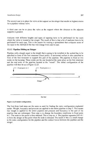
and the end node of the pipeline located at the “vessel”. The initial configuration of the
pipeline will then be as in Figure 12.23.
Fixed point nr.2 Fixed point nr.1
P
Stinger
Sea bed
Figure 12.23 Initial configuration.
The first three load steps are the same as used for finding the static configuration explained
earlier. Weight, buoyancy and pressure are applied to the entire pipeline in step 3. This means
that weight is applied to the entire pipeline and pressure and buoyancy to the part of the
pipeline that are submerged. Next step is to change the boundary conditions in fixed point
nr.1. The node in this point is then released. This is step no. 4. The pipeline separates 0.01-0.1
m from the stinger at this point when the node is released. The result of this is a small change
in the static configuration for the pipeline and the contact forces between the pipeline and the
stinger.