
Page 235 - Pipelines and Risers
P. 235
208 Chapter 12
Fixed pint M.2
I
I
v
Conscntrated
Sea bed
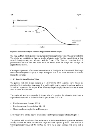
Figure 12.24 Pipeline configuration before the pipeline slides on the stinger.
The next and last step is to move the surface representing the lay-vessehtinger towards left.
The whole lay-vessellstinger has one single reference node. The lay-vessellstinger is then
moved through moving the reference node in Figure 12.24. Point nr.2 remains fixed. A
pipeline cross section will then move from the vessel, over the stinger and through the
sagbend to the seabed.
Convergence problems often occur when the node in fixed point nr.1 is released. The longer
the distance between fixed point nr.2 and fixed point nr.1 is, the more difficult it is to make
the model converge.
12.5.3 Installation of In-line Valve
The purpose with this design example is to illustrate the effect an in-line valve has on the
strain level in the pipeline. Analyses will be performed for valve located in sagbend and valve
located at a support on the stinger. What effect tapering of the pipeline can have on the strain
level will also be illustrated.
The results will also be compared with design criteria’s regarding the allowable strain level in
sagbend and overbend, as defined in Statoil specification F-SD-101.
Pipeline overbend (stinger) 0.23%
Pipeline sagbend (suspended part) 0.15%
No contact between pipeline and last support
Less conservative criteria may be defined based on the principles presented in Chapter 4.
The problem with installation of an in-line valve is the increase in bending moment and strain
locally because the valve has stiffness larger than the adjacent pipeline. The increase in
bending moment because of the fact that the valve has a larger stiffness will occur both in