
Page 215 - Pipelines and Risers
P. 215
188 Chapter 1.2
average value for the radius of curvature that are made of the rollers at the stinger and vessel.
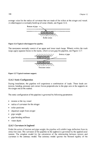
A roller/support is normally build up of some wheels, see Figure 12.6.
Bottom of pipe
Roller centre
Figure 12.6 Typical roller/support for pipeline.
The tensioners normally consist of an upper and lower track loops. Wheels within the track
loops apply squeeze forces to the tracks, which in turn grip the pipeline, see Figure 12.7.
Tensioner centre
Figure 12.7 Typical tensioner support.
12.4.2 Static Configuration
During installation, the pipeline will experience a combination of loads. These loads are:
tension, bending, pressure and contact forces perpendicular to the pipe axis at the supports on
the stinger and at the seabed.
The static configuration of the pipeline is governed by following parameters:
tension at the lay-vessel
0 radius of curvature for the stinger
roller positions
0 departure angle from stinger
pipe weight
0 pipe bending stiffness
0 waterdepth
12.4.3 Curvature in Sagbend
Under the action of tension and pipe weight, the pipeline will exhibit large deflection from its
stress free state. The curvature of the pipeline in the sagbend is governed by the applied axial
tension. The simplest model for the calculation of the relationship between tension and
curvature is the catenary model. The catenary model ignores the flexural rigidity of the