
Page 214 - Pipelines and Risers
P. 214
Installation Design 187
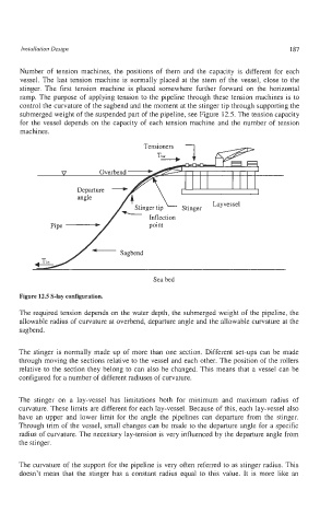
Number of tension machines, the positions of them and the capacity is different for each
vessel. The last tension machine is normally placed at the stem of the vessel, close to the
stinger. The first tension machine is placed somewhere further forward on the horizontal
ramp. The purpose of applying tension to the pipeline through these tension machines is to
control the curvature of the sagbend and the moment at the stinger tip through supporting the
submerged weight of the suspended part of the pipeline, see Figure 12.5. The tension capacity
for the vessel depends on the capacity of each tension machine and the number of tension
machines.
Sea bed
Figure 12.5 S-lay configuration.
The required tension depends on the water depth, the submerged weight of the pipeline, the
allowable radius of curvature at overbend, departure angle and the allowable curvature at the
sagbend.
The stinger is normally made up of more than one section. Different set-ups can be made
through moving the sections relative to the vessel and each other. The position of the rollers
relative to the section they belong to can also be changed. This means that a vessel can be
configured for a number of different radiuses of curvature.
The stinger on a lay-vessel has limitations both for minimum and maximum radius of
curvature. These limits are different for each lay-vessel. Because of this, each lay-vessel also
have an upper and lower limit for the angle the pipelines can departure from the stinger.
Through trim of the vessel, small changes can be made to the departure angle for a specific
radius of curvature. The necessary lay-tension is very influenced by the departure angle from
the stinger.
The curvature of the support for the pipeline is very often referred to as stinger radius. This
doesn’t mean that the stinger has a constant radius equal to this value. It is more like an