
Page 266 - Planning and Design of Airports
P. 266
Geometric Design of the Airfield 227
OIS SURFACE
STARTS AT END
OF CLEARWAY
IF ONE IS IN PLACE
6,000 FEET
15°
300 FEET
600 FEET 20 L C L
300 FEET OBSTACLE IDENTIFICATION
15° SURFACE (OIS) 6,000 FEET
62.5:1
50,000 FEET
STARTS AT
DEPARTURE END
OF RUNWAY (DER)
OR END OF OIS (62.5:1)
CLEARWAY
(IF ONE EXISTS) OIS (62.5:1)
Clearway
Slope SURFACE STARTS AT THE ELEVATION OF
80:1 or 1.25% THE CLEARWAY SURFACE (IF ONE EXISTS)
50,000 FEET
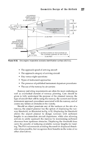
FIGURE 6-31 One engine inoperative obstacle identifi cation surface (62.5:1).
• The approach speed of arriving aircraft
• The approach category of arriving aircraft
• Day versus night operations
• Types of instrument approaches
• The presence of published instrument departure procedures
• The use of the runway by air carriers
Runway end siting requirements are often the most confusing as
well as overlooked element of runway planning. Care should be
given to fully understand the purpose of the planned runway, the
type of aircraft that will be using the runway, the current and future
instrument approach procedures associated with the runway, and of
course any terrain or obstacles in the vicinity.
Should an object penetrate any of the surfaces at the site of a
runway, the airport planner has the option of displacing the run-
way threshold, as illustrated in Fig. 6-32. Displacing the threshold
allows the airport planner to design runways with sufficient
lengths to accommodate aircraft departures, while also allowing
arrivals to safely approach the runway by maintaining sufficient
clearance from upstream obstacles. Displacing the threshold does
carry the penalty of reducing available runway lengths for land-
ing. The FAA recommends avoiding the need for displaced thresh-
olds when possible, but recognizes their benefits in the wake of no
other alternatives.