
Page 388 - Planning and Design of Airports
P. 388
Airport Lighting, Marking, and Signage 339
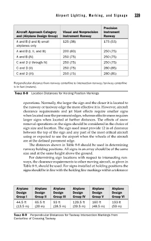
Precision
Aircraft Approach Category Visual and Nonprecision Instrument
and (Airplane Design Group) Instrument Runway Runway
A and B (I and II) small 125 (38) 175 (53)
airplanes only
A and B (I, II, and III) 200 (60) 250 (75)
A and B (IV) 250 (75) 250 (75)
C and D (I through IV) 250 (75) 250 (75)
C and D (V) 250 (75) 280 (85)
C and D (VI) 250 (75) 280 (85)
Perpendicular distance from runway centerline to intersection runway/taxiway centerline
is in feet (meters).
TABLE 8-8 Location Distances for Holding Position Markings
operations. Normally, the larger the sign and the closer it is located to
the runway or taxiway edge the more effective it is. However, aircraft
clearance requirements and jet blast effects require smaller signs
when located near the pavement edges, whereas effectiveness requires
larger signs when located at further distances. The effects of snow
removal operations on the signs should be considered in the choice of
sign size and location. The sign used must provide 12 in of clearance
between the top of the sign and any part of the most critical aircraft
using or expected to use the airport when the wheels of the aircraft
are at the defined pavement edge.
The distances shown in Table 8-8 should be used in determining
runway holding positions. All signs in an array should be of the same
size and at the same height above the ground.
For determining sign locations with respect to intersecting run-
ways, the clearance requirements to other moving aircraft, as given in
Table 8-9, should be used. For signs installed at holding positions the
signs should be in line with the holding line markings within a tolerance
Airplane Airplane Airplane Airplane Airplane Airplane
Design Design Design Design Design Design
Group I Group II Group III Group IV Group V Group VI
44.5 ft 65.5 ft 93 ft 129.5 ft 160 ft 193 ft
(13.5 m) (20 m) (28.5 m) (39.5 m) (48.5 m) (59 m)
TABLE 8-9 Perpendicular Distances for Taxiway Intersection Markings from
Centerline of Crossing Taxiway