
Page 424 - Planning and Design of Airports
P. 424
368 Airp o r t D e sign
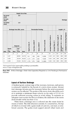
Supply Curve Nos.
For paved 2.0
areas
For bare Drainage
areas
For turfed 1.5
areas
Drainage Area (DA), acres Permissible Ponding Length L, ft
Depth at Inlet, ft Volume 1000 ft 3
Unpaved Pond Area, 1000 ft 2 Volume, ft 3 /acre DA Average Roughness Factor n Average Slope S, % Actual or Effective Length, ft = 0.40 and L for n L Adopted for Selecting Diagrams
Paved, Turf Equivalent = 1%
n = n =
Inlet 0.02 Bare 0.40 Total S
1 2 3 4 5 6 7 8 9 10 11 12 13 14
4 5.97 26.81 32.78 3.0 138 206 6,292 0.33 2.0 525 300 300
3 5.69 25.54 31.23 1.73 145 125 4,016 0.33 2.8 340 200 200
2 5.69 25.54 31.23 2.73 270 368 11,800 0.33 2.8 340 200 200
∗ Not required when appreciable ponding is permissible.
Source: Corps of Engineers [8].
TABLE 9-8 Airfield Drainage—Drain Inlet Capacities Required to Limit Ponding to Permissible
Volumes
Layout of Surface Drainage
A finished grade contour map of the runways, taxiways, and aprons
is extremely helpful for the layout of a storm drain system. Several
trial drainage layouts may be necessary before the most economical
system can be selected. The grades of the storm drain should be such
as to maintain a minimum mean velocity on the order of 2.5 ft/s to
provide sufficient scouring action to avoid silting. To maintain an
adequate cross section for flow at all times, the diameter of the storm
drain should not be less than 12 in.
Water from a drainage area is collected into the storm drain by
means of inlets. The inlet structure consists of a concrete box, the top
of which is covered with a grate made of cast iron, cast steel, or rein-
forced concrete. The grates must support aircraft wheel loads and