
Page 425 - Planning and Design of Airports
P. 425
Airport Drainage 369
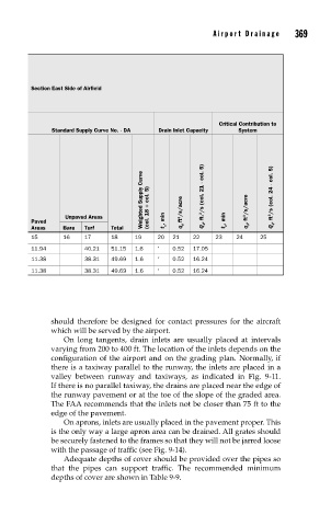
Section East Side of Airfield
Critical Contribution to
Standard Supply Curve No. ¥ DA Drain Inlet Capacity System
Weighted Supply Curve (col. 18 ÷ col. 5) Q d , ft. 3 /s (col. 21 ¥ col. 5) Q d , ft 3 /s (col. 24 ¥ col. 5)
Unpaved Areas ft 3 /s/acre q d , ft 3 /s/acre
Paved t c , min t c , min
Areas Bare Turf Total q d
15 16 17 18 19 20 21 22 23 24 25
11.94 40.21 51.15 1.6 ∗ 0.52 17.05
11.38 38.31 49.69 1.6 ∗ 0.52 16.24
11.38 38.31 49.69 1.6 ∗ 0.52 16.24
should therefore be designed for contact pressures for the aircraft
which will be served by the airport.
On long tangents, drain inlets are usually placed at intervals
varying from 200 to 400 ft. The location of the inlets depends on the
configuration of the airport and on the grading plan. Normally, if
there is a taxiway parallel to the runway, the inlets are placed in a
valley between runway and taxiways, as indicated in Fig. 9-11.
If there is no parallel taxiway, the drains are placed near the edge of
the runway pavement or at the toe of the slope of the graded area.
The FAA recommends that the inlets not be closer than 75 ft to the
edge of the pavement.
On aprons, inlets are usually placed in the pavement proper. This
is the only way a large apron area can be drained. All grates should
be securely fastened to the frames so that they will not be jarred loose
with the passage of traffic (see Fig. 9-14).
Adequate depths of cover should be provided over the pipes so
that the pipes can support traffic. The recommended minimum
depths of cover are shown in Table 9-9.