
Page 58 - Plant design and economics for chemical engineers
P. 58
PROCESS DESIGN DEVELOPMENT 41
HEAT EXCHANGER
Identitication: Item Condenser Date I-I-90
Item No. H-S
No. required I By JRL
Function: Condense overhead uuporsfiom methanolfiactionafion column
Operation: Continuous
Type: Horizontal
Fixed tube sheet
Expansion ring in shell
D u t y 3,400,OOO Btu/h Outside area 470 sq ft
Tube side: Tubea: I in. diam. 14 BWG
Fluid handled Cooling water J.25” Centers A Pattern
Flow rate 380 gpm 225 Tubes each 8 ft long
Pressure 20 psig 2 Passes
Temperature 15°C to 25°C Tube material Carbon steel
Head material Carbon steel
SbeU aide: SkII: 22 in. diam. I Passes
Fluid handled Methanol vapor (Transverse ballks Tube
Flow rate 7OtXJ lb/h support Req’d)
Pressure 0 psiki (Longitudinal bathes 0 Req’d)
Temperature 65°C to (constant temp.) Shell material Carbon steel
Utilities: Untreated cooling water
Controh: Cooling-warer rare controlled by vapor temperature in vent line
Imuhtion: 2-in. rock cork or equivalent; weatherproofed
Tolerances: Tubular Exchangers Manujiiturers Association (TEMA) standards
Comments and drawimp: Location and sizes o/inlets and outlets are shown
on drawing
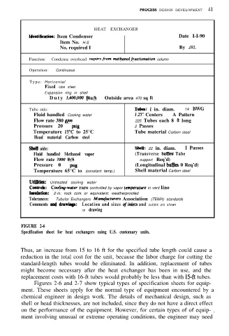
FIGURE 2-6
Specification sheet for heat exchangers using U.S. customary units.
Thus, an increase from 15 to 16 ft for the specified tube length could cause a
reduction in the total cost for the unit, because the labor charge for cutting the
standard-length tubes would be eliminated. In addition, replacement of tubes
might become necessary after the heat exchanger has been in use, and the
replacement costs with 16-ft tubes would probably be less than with 15ft tubes.
Figures 2-6 and 2-7 show typical types of specification sheets for equip-
ment. These sheets apply for the normal type of equipment encountered by a
chemical engineer in design work. The details of mechanical design, such as
shell or head thicknesses, are not included, since they do not have a direct effect
on the performance of the equipment. However, for certain types of of equip- I
ment involving unusual or extreme operating conditions, the engineer may need