
Page 172 - Plastics Engineering
P. 172
Mechanical Behaviour of Plastics 155
During these types of test it is the energy absorbed at fracture, U,, which
is recorded. In terms of the applied force, F,, and sample deformation, 6, this
will be given by
U, = iF,S (2.121)
or expressing this in terms of the compliance, from equation (2.90)
U, = iF:C (2.122)
Now, from equation (2.91) we have the expression for the toughness, G,, of
the material
FZ aC
G -__
‘-2Btk2
So using equation (2.122) and introducing the material width, D
uc
G -- (2.123)
- BD0
where 0 = ((l/C)(i3C/&z))-1. This is a geometrical function which can be
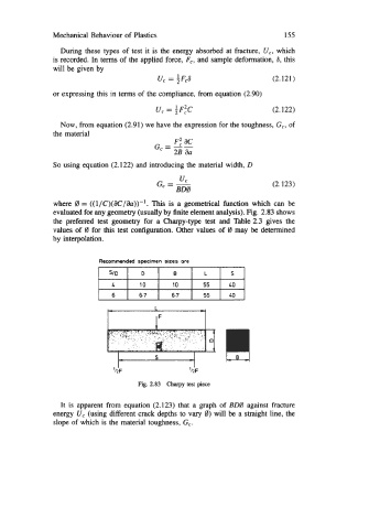
evaluated for any geometry (usually by finite element analysis). Fig. 2.83 shows
the preferred test geometry for a Charpy-type test and Table 2.3 gives the
values of 0 for this test configuration. Other values of 0 may be determined
by interpolation.
Recommended specimen sizes are
6.7 6.7 55
L
IF
Fig. 2.83 Charpy test piece
It is apparent from equation (2.123) that a graph of BDO against fracture
energy U, (using different crack depths to vary 0) will be a straight line, the
slope of which is the material toughness, G,.