
Page 311 - Plastics Engineering
P. 311
294 Processing of Plastics
Substituting (4.24) in (4.23) then
F = nR2Po (L) (4.25)
m+2
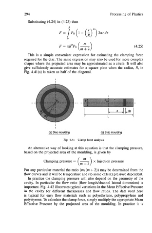
This is a simple convenient expression for estimating the clamping force
required for the disc. The same expression may also be used for more complex
shapes where the projected area may be approximated as a circle. It will also
give sufficiently accurate estimates for a square plate when the radius, R, in
Fig. 4.41(a) is taken as half of the diagonal.
(a) Disc moulding (b) Strip moulding
Fig. 4.41 Clamp force analysis
An alternative way of looking at this equation is that the clamping pressure,
based on the projected area of the moulding, is given by
Clamping pressure = - 2) x Injection pressure
For any particular material the ratio (rn/(rn + 2)) may be determined from the
flow curves and it will be temperature and (to some extent) pressure dependent.
In practice the clamping pressure will also depend on the geometry of the
cavity. In particular the flow ratio (flow lengwchannel lateral dimension) is
important. Fig. 4.42 illustrates typical variations in the Mean Effective Pressure
in the cavity for different thicknesses and flow ratios. The data used here
is typical for easy flow materials such as polyethylene, polypropylene and
polystyrene. To calculate the clamp force, simply multiply the appropriate Mean
Effective Pressure by the projected area of the moulding. In practice it is