
Page 312 - Plastics Engineering
P. 312
Processing of Plastics 295
0 50 100 150 200
Flow ratlo
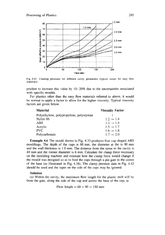
Fig. 4.42 Claming pressures for different cavity geometries (typical values for easy flow
materials)
prudent to increase this value by 10-20% due to the uncertainties associated
with specific moulds.
For plastics other than the easy flow materials referred to above, it would
be normal to apply a factor to allow for the higher viscosity. Typical viscosity
factors are given below.
Material Viscosity Factor
Polyethylene, polypropylene, polystyrene 1
Nylon 66 1.2 -+ 1.4
ABS 1.3 -+ 1.4
Acrylic 1.5 -+ 1.7
PVC 1.6 -+ 1.8
Polycarbonate 1.7 -+ 2.0
Example 4.6 The mould shown in Fig. 4.35 produces four cup shaped ABS
mouldings. The depth of the cups is 60 mm, the diameter at the is 90 mm
and the wall thickness is 1.0 mm. The distance from the sprue to the cavity is
40 mm and the runner diameter is 6 mm. Calculate the clamp force necessary
on the moulding machine and estimate how the clamp force would change if
the mould was designed so as to feed the cups through a pin gate in the centre
of the base (as illustrated in Fig. 4.38). The clamp pressure data in Fig. 4.42
should be used and the taper on the side of the cups may be ignored.
Solution
(a) Within the cavity, the maximum flow length for the plastic melt will be
from the gate, along the side of the cup and across the base of the cup, ie
Flow length = 60 + 90 = 150 mm