
Page 161 - Power Electronic Control in Electrical Systems
P. 161
//SYS21/F:/PEC/REVISES_10-11-01/075065126-CH004.3D ± 149 ± [106±152/47] 17.11.2001 9:54AM
Power electronic control in electrical systems 149
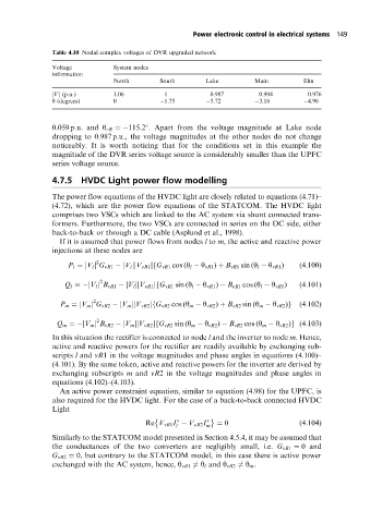
Table 4.10 Nodal complex voltages of DVR upgraded network
Voltage System nodes
information
North South Lake Main Elm
jVj (p.u.) 1.06 1 0.987 0.994 0.976
y (degrees) 0 1.75 5.72 3.18 4.96
0:059 p:u: and y cR 115:2 . Apart from the voltage magnitude at Lake node
dropping to 0.987 p.u., the voltage magnitudes at the other nodes do not change
noticeably. It is worth noticing that for the conditions set in this example the
magnitude of the DVR series voltage source is considerably smaller than the UPFC
series voltage source.
4.7.5 HVDC Light power flow modelling
The power flow equations of the HVDC light are closely related to equations (4.71)±
(4.72), which are the power flow equations of the STATCOM. The HVDC light
comprises two VSCs which are linked to the AC system via shunt connected trans-
formers. Furthermore, the two VSCs are connected in series on the DC side, either
back-to-back or through a DC cable (Asplund et al., 1998).
If it is assumed that power flows from nodes l to m, the active and reactive power
injections at these nodes are
2
P l jV l j G vR1 jV l jjV vR1 j G vR1 cos (y l y vR1 ) B vR1 sin (y l y vR1 ) (4:100)
f
2
Q l jV l j B vR1 jV l jjV vR1 j G vR1 sin (y l y vR1 ) B vR1 cos (y l y vR1 ) (4:101)
f
2
P m jV m j G vR2 jV m jjV vR2 j G vR2 cos (y m y vR2 ) B vR2 sin (y m y vR2 )f g (4:102)
2
Q m jV m j B vR2 jV m jjV vR2 j G vR2 sin (y m y vR2 ) B vR2 cos (y m y vR2 )g (4:103)
f
In this situation the rectifier is connected to node l and the inverter to node m. Hence,
active and reactive powers for the rectifier are readily available by exchanging sub-
scripts l and vR1 in the voltage magnitudes and phase angles in equations (4.100)±
(4.101). By the same token, active and reactive powers for the inverter are derived by
exchanging subscripts m and vR2 in the voltage magnitudes and phase angles in
equations (4.102)±(4.103).
An active power constraint equation, similar to equation (4.98) for the UPFC, is
also required for the HVDC light. For the case of a back-to-back connected HVDC
Light
Re V vR1 I V vR2 I 0 (4:104)
l m
Similarly to the STATCOM model presented in Section 4.5.4, it may be assumed that
the conductances of the two converters are negligibly small, i.e. G vR1 0 and
G vR2 0, but contrary to the STATCOM model, in this case there is active power
exchanged with the AC system, hence, y vR1 6 y l and y vR2 6 y m .