
Page 157 - Power Electronic Control in Electrical Systems
P. 157
//SYS21/F:/PEC/REVISES_10-11-01/075065126-CH004.3D ± 145 ± [106±152/47] 17.11.2001 9:54AM
Power electronic control in electrical systems 145
supplied to the shunt converter, Re V vR I vR satisfies the active power demanded
by the series converter, Re V cR I m . The impedance of the series and shunt trans-
formers, Z cR and Z vR , are included explicitly in the model. The ideal voltage sources
and the constraint power equation given in equations (4.9)±(4.11) are used to derive
this UPFC model.
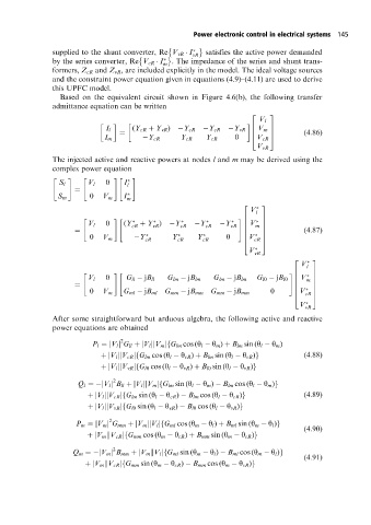
Based on the equivalent circuit shown in Figure 4.6(b), the following transfer
admittance equation can be written
2 3
V l
I l (Y cR Y vR ) Y cR Y cR Y vR 6 V m 7
6 7 (4:86)
I m Y cR Y cR Y cR 0 4 V cR 5
V vR
The injected active and reactive powers at nodes l and m may be derived using the
complex power equation
" # " #" #
0 I
S l V l
l
S m 0 V m I m
2 3
V l
" #" #6 7
V l 0 (Y cR Y ) Y cR Y cR Y 6 V 7
vR
vR 6 m 7 (4:87)
0 V m Y cR Y cR Y cR 0 6 V cR 5
7
6
7
4
V vR
V
2 3
l
" #" #6 7
V l 0 G ll jB ll G lm jB lm G lm jB lm G l0 jB l0 6 V 7
6 m 7
6
7
0 V m G ml jB ml G mm jB mm G mm jB mm 0 6 V 7
4 cR 5
V vR
After some straightforward but arduous algebra, the following active and reactive
power equations are obtained
2
P l V l G ll V l V m jfG lm cos (y l y m ) B lm sin (y l y m )
jjj
jj
(4:88)
jjj
V l V cR j G lm cos (y l y cR ) B lm sin (y l y cR )g
f
f
V l V vR j G l0 cos (y l y vR ) B l0 sin (y l y vR )g
jjj
2
jjj
Q l jV l j B ll V l V m j G lm sin (y l y m ) B lm cos (y l y m )g
f
(4:89)
jjj
f
V l V cR j G lm sin (y l y cR ) B lm cos (y l y cR )g
jjj
V l V vR j G l0 sin (y l y vR ) B l0 cos (y l y vR )g
f
2
j
P m V m j G mm V m j V l G ml cos (y m y l ) B ml sin (y m y l )g
j
jjf
(4:90)
f
j
j
V m j V cR j G mm cos (y m y cR ) B mm sin (y m y cR )g
2
j
f
Q m jV m j B mm V m kV l j G ml sin (y m y l ) B ml cos (y m y l )g
(4:91)
f
j
V m kV cR j G mm sin (y m y cR ) B mm cos (y m y cR )g