
Page 155 - Power Electronic Control in Electrical Systems
P. 155
//SYS21/F:/PEC/REVISES_10-11-01/075065126-CH004.3D ± 143 ± [106±152/47] 17.11.2001 9:54AM
Power electronic control in electrical systems 143
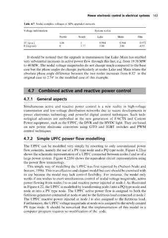
Table 4.7 Nodal complex voltages of SPS upgraded network
Voltage information System nodes
North South Lake Main Elm
jVj (p.u.) 1.06 1 0.984 0.984 0.972
y (degrees) 0 1.77 5.80 3.06 4.95
It should be noticed that the upgrade in transmission line Lake±Main has enabled
very substantial increases in active power flow through this line, e.g. from 19.38 MW
to 40 MW. The nodal voltage magnitudes do not change much compared to the base
case but the phase angles do change; particularly at nodes Lake and Main where the
absolute phase angle difference between the two nodes increases from 0:32 in the
original case to 2:74 in the modified case of this example.
4.7 Combined active and reactive power control
4.7.1 General aspects
Simultaneous active and reactive power control is a new reality in high-voltage
transmission and low-voltage distribution networks due to recent developments in
power electronics technology and powerful digital control techniques. Such tech-
nological advances are embodied in the new generation of FACTS and Custom
Power equipment, such as the UPFC, the DVR and the HVDC light. They are based
on new power electronic converters using GTO and IGBT switches and PWM
control techniques.
4.7.2 Simple UPFC power flow modelling
The UPFC can be modelled very simply by resorting to only conventional power
flow concepts, namely the use of a PV type node and a PQ type node. Figure 4.22(a)
shows the schematic representation of a UPFC connected between nodes l and m of a
large power system. Figure 4.22(b) shows the equivalent circuit representation using
the power flow terminology.
This simple way of modelling the UPFC was first reported by (Nabavi-Niaki and
Iravani, 1996). This is an effective and elegant model but care should be exercised with
its use because the model may lack control flexibility. For instance, the model only
works if one wishes to exert simultaneous control of nodal voltage magnitude, active
power flowing from nodes l to m and reactive power injected at node l. As illustrated
in Figure 4.22, the UPFC is modelled by transforming node l into a PQ type node and
node m into a PV type node. The UPFC active power flow is assigned to both the
fictitious generator connected at node m and to the fictitious load connected at node l.
The UPFC reactive power injected at node l is also assigned to the fictitious load.
Furthermore, the UPFC voltage magnitude at node m is assigned to the newly created
PV type node. It should be remarked that the implementation of this model in a
computer program requires no modification of the code.