
Page 150 - Power Electronic Control in Electrical Systems
P. 150
//SYS21/F:/PEC/REVISES_10-11-01/075065126-CH004.3D ± 138 ± [106±152/47] 17.11.2001 9:54AM
138 Power flows in compensation and control studies
If the STATCOM is connected at node l and it is assumed that its conductance
is negligibly small and that there is no active power exchanged with the AC system,
i.e. G vR 0 and y vR y l
P vR 0
(4:73)
2
Q vR jV vR j B vR jV vR kV l jB vR
Based on these equations, the linearized STATCOM equation is given below, where
the variable voltage magnitude jV vR j is taken to be the state variable
" #
@P l @P l
P l @y l @jV vR j y l
(4:74)
Q vR @Q vR @Q vR jV vR j
@y l @jV vR j
At the end of iteration (r), the variable voltage magnitude jV vR j is updated
(r 1) (r) (r)
jV vR j jV vR j jV vR j (4:75)
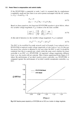
The SVC in the modified five-node network used in Example 5 was replaced with a
STATCOM to maintain nodal voltage magnitude at Lake node at 1 p.u. In this case
the power flow solution is identical to the case when the SVC is used. It should be
remarked that this is a special case, which yields the same result whether the shunt
controller is an SVC or a STATCOM. At regulated voltage magnitudes different
from 1 p.u. the results will not coincide. This is better appreciated from Figure 4.19
where the performance of an ideal reactive power controller, e.g. STATCOM, is
compared against the performance of an ideal variable susceptance controller, e.g.
SVC.
Fig. 4.19 Reactive powers injected by a STATCOM and an SVC as a function of voltage magnitude.