
Page 145 - Power Electronic Control in Electrical Systems
P. 145
//SYS21/F:/PEC/REVISES_10-11-01/075065126-CH004.3D ± 133 ± [106±152/47] 17.11.2001 9:54AM
Power electronic control in electrical systems 133
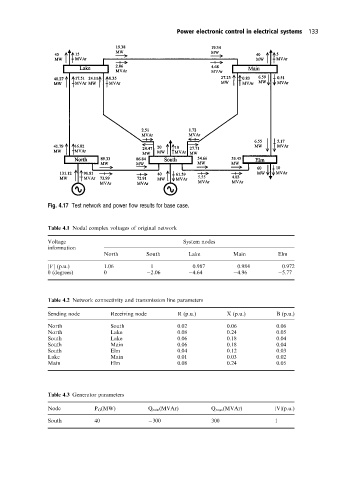
Fig. 4.17 Test networkand power flow results for base case.
Table 4.1 Nodal complex voltages of original network
Voltage System nodes
information
North South Lake Main Elm
jVj (p:u:) 1.06 1 0.987 0.984 0.972
y (degrees) 0 2.06 4.64 4.96 5.77
Table 4.2 Network connectivity and transmission line parameters
Sending node Receiving node R (p.u.) X (p.u.) B (p.u.)
North South 0.02 0.06 0.06
North Lake 0.08 0.24 0.05
South Lake 0.06 0.18 0.04
South Main 0.06 0.18 0.04
South Elm 0.04 0.12 0.03
Lake Main 0.01 0.03 0.02
Main Elm 0.08 0.24 0.05
Table 4.3 Generator parameters
Node P G (MW) Q min (MVAr) Q max (MVAr) |V|(p.u.)
South 40 300 300 1