
Page 146 - Power Electronic Control in Electrical Systems
P. 146
//SYS21/F:/PEC/REVISES_10-11-01/075065126-CH004.3D ± 134 ± [106±152/47] 17.11.2001 9:54AM
134 Power flows in compensation and control studies
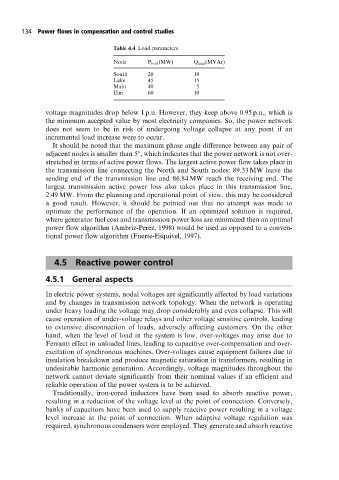
Table 4.4 Load parameters
Node P load (MW) Q load (MVAr)
South 20 10
Lake 45 15
Main 40 5
Elm 60 10
voltage magnitudes drop below 1 p.u. However, they keep above 0.95 p.u., which is
the minimum accepted value by most electricity companies. So, the power network
does not seem to be in risk of undergoing voltage collapse at any point if an
incremental load increase were to occur.
It should be noted that the maximum phase angle difference between any pair of
adjacent nodes is smaller than 5 , which indicates that the power network is not over-
stretched in terms of active power flows. The largest active power flow takes place in
the transmission line connecting the North and South nodes: 89.33 MW leave the
sending end of the transmission line and 86.84 MW reach the receiving end. The
largest transmission active power loss also takes place in this transmission line,
2.49 MW. From the planning and operational point of view, this may be considered
a good result. However, it should be pointed out that no attempt was made to
optimize the performance of the operation. If an optimized solution is required,
where generator fuel cost and transmission power loss are minimized then an optimal
power flow algorithm (Ambriz-Perez, 1998) would be used as opposed to a conven-
tional power flow algorithm (Fuerte-Esquivel, 1997).
4.5 Reactive power control
4.5.1 General aspects
In electric power systems, nodal voltages are significantly affected by load variations
and by changes in transmission network topology. When the network is operating
under heavy loading the voltage may drop considerably and even collapse. This will
cause operation of under-voltage relays and other voltage sensitive controls, leading
to extensive disconnection of loads, adversely affecting customers. On the other
hand, when the level of load in the system is low, over-voltages may arise due to
Ferranti effect in unloaded lines, leading to capacitive over-compensation and over-
excitation of synchronous machines. Over-voltages cause equipment failures due to
insulation breakdown and produce magnetic saturation in transformers, resulting in
undesirable harmonic generation. Accordingly, voltage magnitudes throughout the
network cannot deviate significantly from their nominal values if an efficient and
reliable operation of the power system is to be achieved.
Traditionally, iron-cored inductors have been used to absorb reactive power,
resulting in a reduction of the voltage level at the point of connection. Conversely,
banks of capacitors have been used to supply reactive power resulting in a voltage
level increase at the point of connection. When adaptive voltage regulation was
required, synchronous condensers were employed. They generate and absorb reactive