
Page 149 - Power Electronic Control in Electrical Systems
P. 149
//SYS21/F:/PEC/REVISES_10-11-01/075065126-CH004.3D ± 137 ± [106±152/47] 17.11.2001 9:54AM
Power electronic control in electrical systems 137
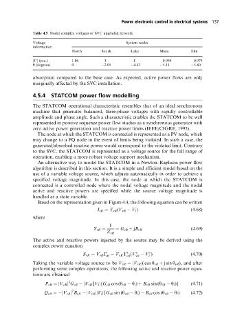
Table 4.5 Nodal complex voltages of SVC upgraded network
Voltage System nodes
information
North South Lake Main Elm
jVj (p.u.) 1.06 1 1 0.994 0.975
y (degrees) 0 2.05 4.83 5.11 5.80
absorption compared to the base case. As expected, active power flows are only
marginally affected by the SVC installation.
4.5.4 STATCOM power flow modelling
The STATCOM operational characteristic resembles that of an ideal synchronous
machine that generates balanced, three-phase voltages with rapidly controllable
amplitude and phase angle. Such a characteristic enables the STATCOM to be well
represented in positive sequence power flow studies as a synchronous generator with
zero active power generation and reactive power limits (IEEE/CIGRE, 1995).
The node at which the STATCOM is connected is represented as a PV node, which
may change to a PQ node in the event of limits being violated. In such a case, the
generated/absorbed reactive power would correspond to the violated limit. Contrary
to the SVC, the STATCOM is represented as a voltage source for the full range of
operation, enabling a more robust voltage support mechanism.
An alternative way to model the STATCOM in a Newton±Raphson power flow
algorithm is described in this section. It is a simple and efficient model based on the
use of a variable voltage source, which adjusts automatically in order to achieve a
specified voltage magnitude. In this case, the node at which the STATCOM is
connected is a controlled node where the nodal voltage magnitude and the nodal
active and reactive powers are specified while the source voltage magnitude is
handled as a state variable.
Based on the representation given in Figure 4.4, the following equation can be written
I vR Y vR (V vR V l ) (4:68)
where
1
Y vR G vR jB vR (4:69)
Z vR
The active and reactive powers injected by the source may be derived using the
complex power equation
S vR V vR I vR V vR Y (V vR V ) (4:70)
vR
l
Taking the variable voltage source to be V vR jV vR j(cos y vR j sin y vR ), and after
performing some complex operations, the following active and reactive power equa-
tions are obtained
2
P vR jV vR j G vR jV vR kV l jfG vR cos (y vR y l ) B vR sin (y vR y l )g (4:71)
2
Q vR jV vR j B vR jV vR kV l jfG vR sin (y vR y l ) B vR cos (y vR y l ) (4:72)